The electric nosewheel steering operates only on
the ground. When the system is engaged, steer-
ing commands from a rudder pedal followup are
supplied to a computer-amplifier. The computer-
amplifier determines the amount and direction
that a DC electric motor deflects the nosewheel.
Lear 20 series airplanes may have either variable
or nonvariable authority nosewheel steering.
The following Landing Gear, Brakes, and
Nosewheel Steering sections describe the
operation of those systems. Model 23 differ-
ences are presented later in the chapter.
LANDING GEAR
INDICATING SYSTEM
General
The landing gear position indicating system con-
sists of three red lights and three green lights, a
test switch, and an aural warning horn.
Gear Position Lights
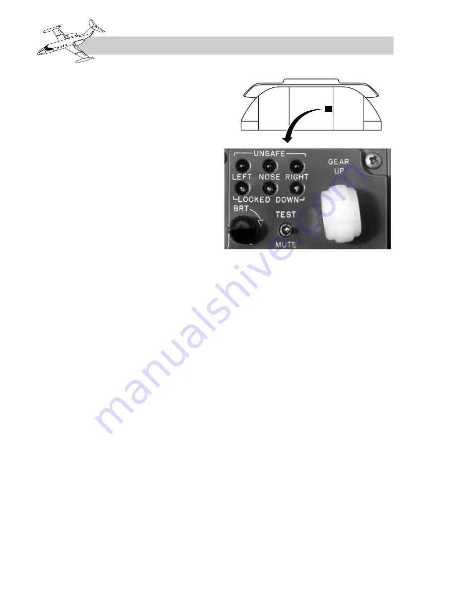
The three green LOCKED DOWN lights (Figure
14-1) are illuminated by their respective down-
lock switches on the gear actuators.
As each gear locks down, the corresponding
green LOCKED DOWN light illuminates.
During gear retraction, the lights extinguish
when the downlocks are hydraulically released.
The nose gear red UNSAFE light is illuminated
when the gear is unsafe or in transit. When the
nose gear is locked in either the up or the down
position, the light extinguishes.
The two main gear red UNSAFE lights illumi-
nate whenever the respective inboard gear door
is unlocked. As each inboard door latches up
(during extension or retraction), the correspond-
ing red light extinguishes.
Indications for gear down-and-locked, up-and-
locked, and in-transit conditions are shown in
Figure 14-2.
If the gear is extended with the emergency air
system, all three green lights and the two main
gear red lights will be illuminated since both
main gear doors will remain fully extended.
The landing gear position lights are tested by
holding the TEST–MUTE switch on the landing
gear control panel in the TEST position. All six
lights will illuminate and the warning horn will
sound. The lights can be dimmed with the dim-
ming rheostat (Figure 14-2), provided the navi-
gation lights are on; otherwise they will be at
maximum intensity.
Circuitry related to the left and right main gear
green position lights may be common with the
landing/taxi light for that side. Confirmation of
main gear downlocking (after bulb testing) can
be made by switching on the respective LDG
LTS switch.
Nose gear green light circuitry may be common
with the engine synchronizing system (if
installed). Confirmation of nose gear downlocking
(after bulb testing) is made by positioning the
ENG SYNC switch on the pedestal to ENG
SYNC (on) and observing that the amber ENG
SYNC light on the annunciator panel illuminates.
14-2
FOR TRAINING PURPOSES ONLY
LEARJET 20 SERIES PILOT TRAINING MANUAL
FlightSafety
international
Figure 14-1.
Gear Selector Switch and
Position Lights (Typical)


