retain the drainage from three engine shut-
downs. Following this, the canister itself must
be drained; otherwise, it will begin to dump
the collected fuel overboard.
Operation
Figure 7-11 illustrates operation of the fuel
system and the associated variable geometry
and engine overspeed systems.
IGNITION SYSTEM
The ignition system consists of an ignition
exciter and two igniters.
The igniter exciter is a solid-state unit with ex-
tended duty capability. In operation, a 28-volt
DC input is supplied to the ignition generator
from the airframe batteries or generators. The
charging circuit converts the input voltage to
interrupted or pulsating DC and supplies it to
the primary winding of the transformer. The
transformer steps up the 28-volt pulsating DC
input to 3,000 volts.
The igniter plugs are self-ionizing, shunted
gap-type igniters designed for relatively low
voltage application.
Control
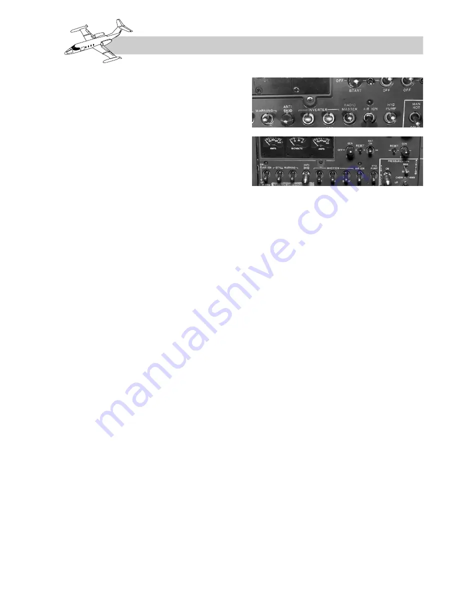
Automatic ignition occurs during engine start-
ing when the GEN switch (Figure 7-12) is
moved to START, and the associated thrust
l eve r i s m ove d f r o m C U T O F F t o I D L E .
Ignition is terminated when the GEN switch
is moved to OFF or GEN position.
Selective ignition provides for continuous
operation of the ignition system when the
two-position AIR IGN switch on the center
switch panel (Figure 7-12) is moved to the
ON position.
AIR SYSTEMS
The engine air systems consist of a primary air
system and the engine bleed-air system.
The primary air system (see Figure 7-1) is
that portion of the engine air system which
is associated partly with combustion and
partly with the direct cooling. It is described
as follows:
The combustion air system is that portion of
the primary air system which is directly asso-
ciated with combustion and thrust. The vari-
able inlet guide vanes in the front frame
annulus guide the air into the compressor for
optimum airflow. The air passes through the
compressor and is diffused in the mainframe.
It is then mixed with fuel in the combustion
section and ignited. The combustion gases
then pass through the turbine where the greater
portion of available energy is used to drive the
engine compressor. The remainder passes
through the exhaust core and tailpipe to pro-
vide thrust. The flow of primary cooling air
around the inner and outer surfaces of the
combustion liner cools the liner and the tur-
bine area. The cooling air then combines with
the combustion airstream.
The pressurizing system provides air through
passages in the engine components to pressur-
ize the oil seals and the engine lube system.
Compressor discharge leakage air flows across
the compressor eighth-stage air seal and pres-
surizes the No. 2 bearing carbon seal. Part of this
air circulates through the compressor rotor in-
terior to pressurize the No. 1 bearing carbon seal.
Part of the combustion section cooling air
flows into the balance piston chamber through
7-13
FOR TRAINING PURPOSES ONLY
LEARJET 20 SERIES PILOT TRAINING MANUAL
FlightSafety
international
Figure 7-12. Center Switch Panel


