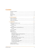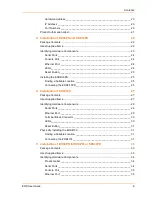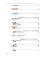
Contents
EDS User Guide
9
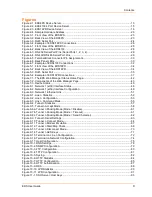
Figures
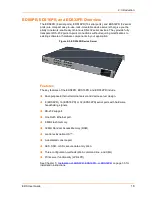
Figure 2-1. EDS8PS Device Server......................................................................................................13
Figure 2-2. EDS4100 4 Port Device Server..........................................................................................15
Figure 2-3. EDS16PR Device Server ...................................................................................................16
Figure 2-4. Sample Hardware Address ................................................................................................20
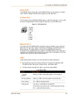
Figure 3-1. Front View of the EDS8PS .................................................................................................23
Figure 3-2. Back View of the EDS8PS .................................................................................................23
Figure 3-3. RJ45 Serial Port .................................................................................................................24
Figure 3-4. Example of EDS8/16PS Connections ................................................................................26
Figure 4-1. Front View of the EDS4100 ................................................................................................28
Figure 4-2. Back View of the EDS4100 ................................................................................................28
Figure 4-3. RS-232 Serial Port Pins (Serial Ports 1, 2, 3, 4) ................................................................29
Figure 4-4. RS-422/RS-485 Serial Port Pins ........................................................................................29
Figure 4-5. Terminal Block Connector Pin Assignments ......................................................................30
Figure 4-6. Back Panel LEDs................................................................................................................30
Figure 4-7. Example of EDS4100 Connections ....................................................................................32
Figure 5-1. Front View of the EDS16PR ...............................................................................................34
Figure 5-2. Back View of the EDS16PR ...............................................................................................34
Figure 5-3. RJ45 Serial Port .................................................................................................................35
Figure 5-4. Example of EDS16PR Connections ...................................................................................37
Figure 7-1. The EDS Web Manager Status Home Page ......................................................................42
Figure 7-2. Components of the Web Manager Page ............................................................................43
Figure 7-3. Device Status .....................................................................................................................46
Figure 8-1. Network 1 (eth0) Interface Status.......................................................................................48
Figure 8-2. Network 1 (eth0) Interface Configuration ...........................................................................49
Figure 8-3. Network 1 Ethernet Link .....................................................................................................51
Figure 9-1. Line n Statistics ..................................................................................................................52
Figure 9-2. Line n Configuration ...........................................................................................................53
Figure 9-3. Line n Command Mode ......................................................................................................55
Figure 9-4. Tunnel n Statistics ..............................................................................................................57
Figure 9-5. Tunnel n Accept Mode .......................................................................................................58
Figure 9-6a. Tunnel n Packing Mode (Mode = Disable) .......................................................................61
Figure 9-7b. Tunnel n Packing Mode (Mode = Timeout) ......................................................................61
Figure 9-8c. Tunnel n Packing Mode (Mode = Send Character) ..........................................................62
Figure 9-9. Tunnel n Serial Settings .....................................................................................................63
Figure 9-10. Tunnel n Connect Mode ...................................................................................................64
Figure 9-11. Tunnel n Modem Emulation .............................................................................................67
Figure 9-12. Tunnel n Start/Stop Chars ................................................................................................69
Figure 9-13. Tunnel n Disconnect Mode...............................................................................................70
Figure 9-14. Tunnel n AES Keys ..........................................................................................................71
Figure 9-15. Terminal on Line n Configuration .....................................................................................72
Figure 9-16. Terminal on Network Configuration..................................................................................74
Figure 9-17. Host Configuration............................................................................................................75
Figure 10-1. DNS Settings ....................................................................................................................78
Figure 10-2. SNMP Configuration.........................................................................................................79
Figure 10-3. FTP Configuration ............................................................................................................80
Figure 10-4. TFTP Configuration ..........................................................................................................81
Figure 10-5. Syslog ...............................................................................................................................82
Figure 10-6. HTTP Statistics.................................................................................................................84
Figure 10-7. HTTP Configuration..........................................................................................................85
Figure 10-8. HTTP Authentication ........................................................................................................87
Figure 10-9. RSS ..................................................................................................................................89
Figure 10-10. LPD Statistics .................................................................................................................90
Figure 10-11. LPD Configuration ..........................................................................................................91
Figure 11-1. SSH Server: Host Keys ....................................................................................................93


