68
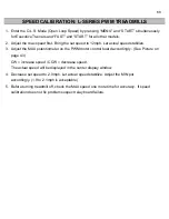
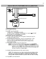
SPEED CALIBRATION: L-SERIES PWM TREADMILLS
1. Enter the O.L.S. Mode (Open Loop Speed) by pressing “MENU” and “START” simultaneously
for Executive Trainers and “FAST” and “START” for all other models.
2. Adjust the max speed first. Bring the set speed to 12mph. Let actual speed stabilize.
3. Adjust the MAX potentiometer on the PWM motor control board accordingly. (See Picture on
page 43)
CW = increase speed / CCW = decrease speed.
The actual speed will be displayed in the center display window.
4. Decrease set speed to 2.0mph. Let actual speed stabilize. Adjust the MIN pot
accordingly. (1.9 to 2.1mph is acceptable)
5. Before turning treadmill off, check the MAX speed one more time for accuracy. If speed
calibration does not fix problem suspect relay board failure.
Summary of Contents for Cardio Trainer L8
Page 5: ...5 ...
Page 27: ...27 Section 3 Parts Identification L8 L9 BED EXPLODED VIEW 18 ...
Page 28: ...28 L7 BED EXPLODED VIEW L Series Upright ...
Page 29: ...29 L SERIES UPRIGHT EXPLODED VIEW 112 ...
Page 30: ...30 L SERIES MOTOR PAN EXPLODED VIEW 111 ...
Page 35: ...35 COMMERCIAL MOTOR PAN SCR MOTOR CONTROL BOARD ...
Page 36: ...36 L SERIES 110V COMMERCIAL LOWER WIRE SCHEMATIC ...
Page 37: ...37 L SERIES 220V COMMERCIAL LOWER WIRE SCHEMATIC ...
Page 40: ...40 L SERIES SCR UPPER WIRE HARNESS WIRING DIAGRAM ...
Page 42: ...42 L SERIES HOME MOTOR PAN WIRING SCHEMATIC ...
Page 47: ...47 L SERIES HOME MOTOR PAN WIRING SCHEMATIC PWM MOTOR CONTROL BOARD W RELAY ASSEMBLY ...
Page 48: ...48 PWM MOTOR CONTROL BOARD W RELAY ASSEMBLY ...
Page 49: ...49 L SERIES PWM UPPER WIRE HARNESS WIRING DIAGRAM ...
Page 50: ...50 EXECUTIVE TRAINER LCD WIRING SCHEMATIC ...
Page 110: ...110 L SERIES ROAD RUNNER LOWER WIRING DIAGRAM ...
Page 111: ...111 L SERIES ROAD RUNNER UPPER WIRING SCHEMATIC ...

