62
SPEED SENSOR
The speed sensor can be checked for proper operation by entering the Open Loop Speed Mode.
(See page 56) There is a yellow SPD LED mounted to either the relay board (HOME PWM
models) or the SCR board (LTD and CLUB models). The light will flash ON and OFF when you
rotate the drive motor flywheel slowly by hand. This indicates the proper operation of the speed
sensor. If you do not get this flashing to occur, then check for proper speed sensor alignment. If
this does not help, replace the speed sensor.
3. DISPLAY COMPONENTS
12 VDC POWER SUPPLY
Measure across the input terminals for AC line voltage (120/220VAC). Measure across the output
wires for DC voltage (12.0VDC to 17.0VDC is acceptable). If you confirm proper input voltage (AC)
and have no output voltage (DC) the DC power supply must be replaced.
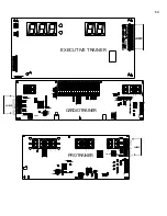
UPPER DISPLAY BOARD
The upper display board is powered by DC voltage. On HOME treadmills this DC voltage is
supplied by the DC power supply. On LTD/CLUB treadmills the SCR board supplies this DC
voltage. Confirm the upper display is getting DC voltage delivered to it. If the display board has the
proper DC voltage supplied and does not light, it must be replaced.
FACEPLATE
The faceplate has no mechanical or electrical components that can fail. However, if you press a
key and it fails to respond check for proper display board spacing. The faceplate is designed as a
passive panel. When the user presses a key (pushes through the faceplate) they activate a switch
mounted on the upper display board. If the display board to face plate distance is too great, the
display board switch will not be fully activated and result in a dead response. Small washers are
placed between the display board and mounting studs to adjust this distance. This is performed at
the factory but can be upset if disassembled in the field.
MEMBRANE PANEL
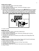
The membrane panel has small micro switches laminated inside that transmit the user’s
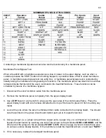
commands into treadmill functions. Enter “Diagnostic Mode” to confirm proper operation of the
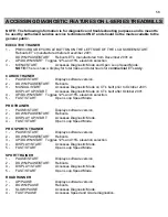
membrane panel. In this test mode you will be able to check each key on the membrane panel. By
pressing a key, you will hear an audible beep and also see a numeric code appear in the speed
window. There is a numeric code assigned to each key on the panel (except the OFF key). For a
complete list of these codes, see the chart on opposite page. If you do not hear a “BEEP” or see
the proper code appear the key is bad and the membrane panel must be replaced.
Summary of Contents for Cardio Trainer L8
Page 5: ...5 ...
Page 27: ...27 Section 3 Parts Identification L8 L9 BED EXPLODED VIEW 18 ...
Page 28: ...28 L7 BED EXPLODED VIEW L Series Upright ...
Page 29: ...29 L SERIES UPRIGHT EXPLODED VIEW 112 ...
Page 30: ...30 L SERIES MOTOR PAN EXPLODED VIEW 111 ...
Page 35: ...35 COMMERCIAL MOTOR PAN SCR MOTOR CONTROL BOARD ...
Page 36: ...36 L SERIES 110V COMMERCIAL LOWER WIRE SCHEMATIC ...
Page 37: ...37 L SERIES 220V COMMERCIAL LOWER WIRE SCHEMATIC ...
Page 40: ...40 L SERIES SCR UPPER WIRE HARNESS WIRING DIAGRAM ...
Page 42: ...42 L SERIES HOME MOTOR PAN WIRING SCHEMATIC ...
Page 47: ...47 L SERIES HOME MOTOR PAN WIRING SCHEMATIC PWM MOTOR CONTROL BOARD W RELAY ASSEMBLY ...
Page 48: ...48 PWM MOTOR CONTROL BOARD W RELAY ASSEMBLY ...
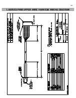
Page 49: ...49 L SERIES PWM UPPER WIRE HARNESS WIRING DIAGRAM ...
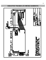
Page 50: ...50 EXECUTIVE TRAINER LCD WIRING SCHEMATIC ...
Page 110: ...110 L SERIES ROAD RUNNER LOWER WIRING DIAGRAM ...
Page 111: ...111 L SERIES ROAD RUNNER UPPER WIRING SCHEMATIC ...


