124
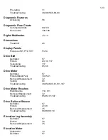
Picture 30,35,41
Removal/Replacement
72,73
Testing
60
Troubleshooting
38,46,90,103,108
Wiring
36,37,42,47,74,110
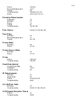
Elevation Potentiometer
Calibration
74
Definition
57
Picture 74
Testing
61
Troubleshooting
39,103,108
Error Codes
93,94,101-103,106-108
Face Plate
Definition
58
Removal/Replacement
71
Testing 62,
105
Frame (Side)
Definition
58
Picture 27,
28
Frame Covers (Side)
Definition
58
Picture 27,
28
Fuses
Picture 35,41,48
Troubleshooting
100,105
Heart Rate Control
Contact Heart Rate
55
Installation
78,79
Troubleshooting
80
IR Potentiometer
Definition
67
Adjustments
58
Picture 41,42,43,44,47
Troubleshooting
66,67
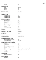
L5 (LS) Error Code
Definition
93
Troubleshooting
93,95,101,102,106,107
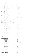
LCD Display Executive Trainer
Picture 53
Troubleshooting
95-98
Summary of Contents for Cardio Trainer L8
Page 5: ...5 ...
Page 27: ...27 Section 3 Parts Identification L8 L9 BED EXPLODED VIEW 18 ...
Page 28: ...28 L7 BED EXPLODED VIEW L Series Upright ...
Page 29: ...29 L SERIES UPRIGHT EXPLODED VIEW 112 ...
Page 30: ...30 L SERIES MOTOR PAN EXPLODED VIEW 111 ...
Page 35: ...35 COMMERCIAL MOTOR PAN SCR MOTOR CONTROL BOARD ...
Page 36: ...36 L SERIES 110V COMMERCIAL LOWER WIRE SCHEMATIC ...
Page 37: ...37 L SERIES 220V COMMERCIAL LOWER WIRE SCHEMATIC ...
Page 40: ...40 L SERIES SCR UPPER WIRE HARNESS WIRING DIAGRAM ...
Page 42: ...42 L SERIES HOME MOTOR PAN WIRING SCHEMATIC ...
Page 47: ...47 L SERIES HOME MOTOR PAN WIRING SCHEMATIC PWM MOTOR CONTROL BOARD W RELAY ASSEMBLY ...
Page 48: ...48 PWM MOTOR CONTROL BOARD W RELAY ASSEMBLY ...
Page 49: ...49 L SERIES PWM UPPER WIRE HARNESS WIRING DIAGRAM ...
Page 50: ...50 EXECUTIVE TRAINER LCD WIRING SCHEMATIC ...
Page 110: ...110 L SERIES ROAD RUNNER LOWER WIRING DIAGRAM ...
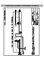
Page 111: ...111 L SERIES ROAD RUNNER UPPER WIRING SCHEMATIC ...


