125
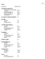
Wiring
50
LED LIGHTS
SCR
38,
39
PWM
44
RELAY
46
Maintenance
119-121
Medical Rails
Installation-L7 81
Installation-L8 82,83
Installation-L9 84-87
Membrane Panel
Button
codes
63
Bypass
Test
63-64
Definition
58
Picture 51-54
Removal/Replacement
71
Testing
62
Troubleshooting
101
Noises
88-91
O5 (OS) Error Code
93,94,96
Parts List
31-34
PO Error Code
95,96,103,108
Power Cord (Line Cord)
Removal/Replacement
69
Troubleshooting
100,105
PWM Motor Control Board
Definition
58
LED
Lights
44
Picture 41,48
Removal/Replacement
69
Testing
61
Troubleshooting
43,44,61,67,68,91,92,106,107
Wiring
42,47,110
Voltage 43
Rebooting
Executive
Trainer
56,
Relay Board
Definition
56
Summary of Contents for Cardio Trainer L8
Page 5: ...5 ...
Page 27: ...27 Section 3 Parts Identification L8 L9 BED EXPLODED VIEW 18 ...
Page 28: ...28 L7 BED EXPLODED VIEW L Series Upright ...
Page 29: ...29 L SERIES UPRIGHT EXPLODED VIEW 112 ...
Page 30: ...30 L SERIES MOTOR PAN EXPLODED VIEW 111 ...
Page 35: ...35 COMMERCIAL MOTOR PAN SCR MOTOR CONTROL BOARD ...
Page 36: ...36 L SERIES 110V COMMERCIAL LOWER WIRE SCHEMATIC ...
Page 37: ...37 L SERIES 220V COMMERCIAL LOWER WIRE SCHEMATIC ...
Page 40: ...40 L SERIES SCR UPPER WIRE HARNESS WIRING DIAGRAM ...
Page 42: ...42 L SERIES HOME MOTOR PAN WIRING SCHEMATIC ...
Page 47: ...47 L SERIES HOME MOTOR PAN WIRING SCHEMATIC PWM MOTOR CONTROL BOARD W RELAY ASSEMBLY ...
Page 48: ...48 PWM MOTOR CONTROL BOARD W RELAY ASSEMBLY ...
Page 49: ...49 L SERIES PWM UPPER WIRE HARNESS WIRING DIAGRAM ...
Page 50: ...50 EXECUTIVE TRAINER LCD WIRING SCHEMATIC ...
Page 110: ...110 L SERIES ROAD RUNNER LOWER WIRING DIAGRAM ...
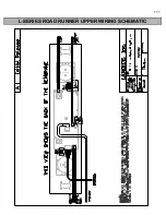
Page 111: ...111 L SERIES ROAD RUNNER UPPER WIRING SCHEMATIC ...

