113
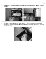
3.
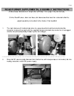
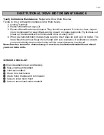
Route the CD changer harness behind the elevation motor, then around the back of the CD
changer.
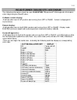
4.
Insert the connector into the side of the changer. It will snap when properly connected.
Examine all wires around the elevation motor and drive motor to be sure they will not contact
any moving parts.
Summary of Contents for Cardio Trainer L8
Page 5: ...5 ...
Page 27: ...27 Section 3 Parts Identification L8 L9 BED EXPLODED VIEW 18 ...
Page 28: ...28 L7 BED EXPLODED VIEW L Series Upright ...
Page 29: ...29 L SERIES UPRIGHT EXPLODED VIEW 112 ...
Page 30: ...30 L SERIES MOTOR PAN EXPLODED VIEW 111 ...
Page 35: ...35 COMMERCIAL MOTOR PAN SCR MOTOR CONTROL BOARD ...
Page 36: ...36 L SERIES 110V COMMERCIAL LOWER WIRE SCHEMATIC ...
Page 37: ...37 L SERIES 220V COMMERCIAL LOWER WIRE SCHEMATIC ...
Page 40: ...40 L SERIES SCR UPPER WIRE HARNESS WIRING DIAGRAM ...
Page 42: ...42 L SERIES HOME MOTOR PAN WIRING SCHEMATIC ...
Page 47: ...47 L SERIES HOME MOTOR PAN WIRING SCHEMATIC PWM MOTOR CONTROL BOARD W RELAY ASSEMBLY ...
Page 48: ...48 PWM MOTOR CONTROL BOARD W RELAY ASSEMBLY ...
Page 49: ...49 L SERIES PWM UPPER WIRE HARNESS WIRING DIAGRAM ...
Page 50: ...50 EXECUTIVE TRAINER LCD WIRING SCHEMATIC ...
Page 110: ...110 L SERIES ROAD RUNNER LOWER WIRING DIAGRAM ...
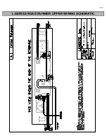
Page 111: ...111 L SERIES ROAD RUNNER UPPER WIRING SCHEMATIC ...


