63
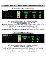
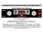
MEMBRANE PANEL BUTTON CODES
CODE
#
Executive
Trainer
Cardio
Trainer
Pro
Trainer
Pro Sports
Trainer
Sport
Trainer
1
LEFT 1 (TOP)
MANUAL
START
START
START
2 LEFT
2
PROGRAMS
N/A PAUSE
PAUSE
3 LEFT
3 CARDIO
PAUSE
DISPLAY
DISPLAY
4
LEFT 4 (BOTTOM)
UP
DISPLAY UP
PROGRAM SELECT
FAST
5
RIGHT 1 (TOP)
DOWN
DISPLAY DOWN
FAST
SLOW
6
RIGHT 2
DISPLAY UP
FAST
SLOW
UP
7
RIGHT 3
DISPLAY DOWN
SLOW
UP
DOWN
8
RIGHT 4 (BOTTOM)
FAST
UP
DOWN
9 PREV SLOW
DOWN
10 MENU START
FAT
BURN
11 NEXT PAUSE
INTERMED
12 START
ADVANCED
13 PAUSE
INTERVALS
14 FAST
HRC
15 SLOW
16 UP
17 DOWN
Conducting a membrane bypass test can also test the functionality of a membrane panel.
Membrane Panel Bypass Test
When a treadmill with a membrane experiences a loss in power to the upper display, such as when a
customer presses the START button and nothing happens, a possible cause of this is a bad membrane
panel. A membrane panel bypass test can verify this. A membrane panel bypass test is conducted by
literally taking the membrane and bypassing its functions. The membrane panel has small micro switches
laminated inside that transmit the user’s commands into treadmill functions. These functions can be
simulated by means of a membrane bypass:
1. Disconnect the silver foil ribbon cable from the membrane panel.
2. Remove the membrane panel completely from the upper display board.
3. Use a
DRY
towel or a terry-cloth to wrap over the open area of the control panel frame. Place the
upper display board with wire harness still attached on top of the towel to prevent it from touching any
metal.
4. Look at the pins where the silver membrane ribbon cable connected to the display board. You should
note that printed on the green circuit board behind each pin is it’s specific function.
5. Using a jumper (i.e. a jumper wire with two copper ends, a paper clip, or a voltmeter set to continuity)
bypass the start button by touching one end of the jumper to the pin labeled
GND
or
GROUND
, and the
other end of the jumper to the pin labeled
START
or
ON
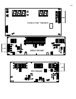
. (Note on page 2 where to locate these pins
on various Landice display boards) If the membrane is bad the treadmill will turn on and read
“SAFE.”
6. If it is necessary, replace the damaged membrane panel.
Summary of Contents for Cardio Trainer L8
Page 5: ...5 ...
Page 27: ...27 Section 3 Parts Identification L8 L9 BED EXPLODED VIEW 18 ...
Page 28: ...28 L7 BED EXPLODED VIEW L Series Upright ...
Page 29: ...29 L SERIES UPRIGHT EXPLODED VIEW 112 ...
Page 30: ...30 L SERIES MOTOR PAN EXPLODED VIEW 111 ...
Page 35: ...35 COMMERCIAL MOTOR PAN SCR MOTOR CONTROL BOARD ...
Page 36: ...36 L SERIES 110V COMMERCIAL LOWER WIRE SCHEMATIC ...
Page 37: ...37 L SERIES 220V COMMERCIAL LOWER WIRE SCHEMATIC ...
Page 40: ...40 L SERIES SCR UPPER WIRE HARNESS WIRING DIAGRAM ...
Page 42: ...42 L SERIES HOME MOTOR PAN WIRING SCHEMATIC ...
Page 47: ...47 L SERIES HOME MOTOR PAN WIRING SCHEMATIC PWM MOTOR CONTROL BOARD W RELAY ASSEMBLY ...
Page 48: ...48 PWM MOTOR CONTROL BOARD W RELAY ASSEMBLY ...
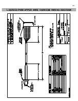
Page 49: ...49 L SERIES PWM UPPER WIRE HARNESS WIRING DIAGRAM ...
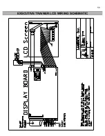
Page 50: ...50 EXECUTIVE TRAINER LCD WIRING SCHEMATIC ...
Page 110: ...110 L SERIES ROAD RUNNER LOWER WIRING DIAGRAM ...
Page 111: ...111 L SERIES ROAD RUNNER UPPER WIRING SCHEMATIC ...

