52
L-SERIES DISPLAY CONTROL PANELS & FEATURES PART 2
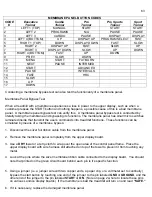
L-Series Pro Sports Trainer Faceplate
Models That Use This Faceplate:
L7-PST, L8-PST, L7-LTD-PST, L8-LTD-PST, L7-CLUB-PST, L8-CLUB-PST,
L9-CLUB-PST(110V) & L9-CLUB-PST(220V)
Production Time Frame:
2001-Present
Electronics:
:
PWM motor pan on all Home Units, 110V SCR commercial motor pan for LTD’s and
110V CLUB’s, 220V SCR commercial motor pan for 220V CLUB units. See Wiring Diagrams.
Settings Used In:
Home and Commercial (LTD’s and CLUB’s)
Key Features:
Closed Loop Treadmill (w/ speed sensor), Safety Lanyard, 0.5-12MPH Push Button
Speed and Elevation Control (11MPH on LTD’s and CLUB’s), 4 Built in Programs, 2 User Defined
Programs.
L-Series Pro Trainer Membrane
Models That Use This Membrane:
L7-PT, L8-PT, L7-LTD-PT, L8-LTD-PT, L7-CLUB-PT, L8-CLUB-PT.
Production Time Frame:
1999-Present
Electronics:
:
PWM motor pan on all Home Units, 110V SCR commercial motor pan for LTD’s and
110V CLUB’s, 220V SCR commercial motor pan for 220V CLUB units. See Wiring Diagrams.
Settings Used In:
Home and Commercial (LTD’s and CLUB’s)
Key Features:
Closed Loop Treadmill (w/ speed sensor), Safety Lanyard, 0.5-12MPH Push Button
Speed and Elevation Control (11MPH on LTD’s and CLUB’s), 5 Built in Programs, 5 User Defined
Programs, Optional Wireless Heart-Rate Control.
Summary of Contents for Cardio Trainer L8
Page 5: ...5 ...
Page 27: ...27 Section 3 Parts Identification L8 L9 BED EXPLODED VIEW 18 ...
Page 28: ...28 L7 BED EXPLODED VIEW L Series Upright ...
Page 29: ...29 L SERIES UPRIGHT EXPLODED VIEW 112 ...
Page 30: ...30 L SERIES MOTOR PAN EXPLODED VIEW 111 ...
Page 35: ...35 COMMERCIAL MOTOR PAN SCR MOTOR CONTROL BOARD ...
Page 36: ...36 L SERIES 110V COMMERCIAL LOWER WIRE SCHEMATIC ...
Page 37: ...37 L SERIES 220V COMMERCIAL LOWER WIRE SCHEMATIC ...
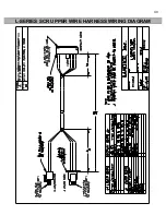
Page 40: ...40 L SERIES SCR UPPER WIRE HARNESS WIRING DIAGRAM ...
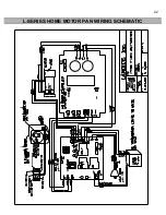
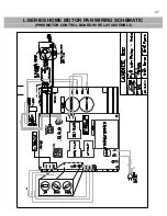
Page 42: ...42 L SERIES HOME MOTOR PAN WIRING SCHEMATIC ...
Page 47: ...47 L SERIES HOME MOTOR PAN WIRING SCHEMATIC PWM MOTOR CONTROL BOARD W RELAY ASSEMBLY ...
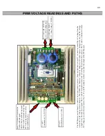
Page 48: ...48 PWM MOTOR CONTROL BOARD W RELAY ASSEMBLY ...
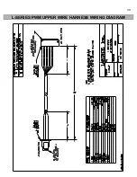
Page 49: ...49 L SERIES PWM UPPER WIRE HARNESS WIRING DIAGRAM ...
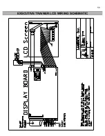
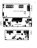
Page 50: ...50 EXECUTIVE TRAINER LCD WIRING SCHEMATIC ...
Page 110: ...110 L SERIES ROAD RUNNER LOWER WIRING DIAGRAM ...
Page 111: ...111 L SERIES ROAD RUNNER UPPER WIRING SCHEMATIC ...


