2
Service Manual Version C/D.2
Page 2-3
Table of Contents
SECTION 1- Introduction
Page 4
How to Use this Manual
Page 5-14
Replica Landice Warranty Cards and Warranty Policy
Page 15
Service Authorization Form
Page 16
Time Allotted for Repairs
Page 17-18
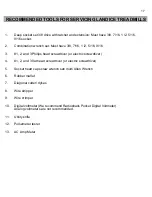
Tools Needed for Repairs
SECTION 2- Installation
Page 19-21
Safety Warnings
Page 22
Electrical Requirements for L-Series Treadmills
Page 23-25
Treadmill Assembly and Installation Instructions
Page 26
Treadmill’s General Dimensions
SECTION 3- - Parts Identification
Exploded View of L7 & L8/L9
Page 27
L8/L9 Bed
Page 28
L7 Bed
Page 29
L-Series Upright
Page 30
L-Series Motor Pan and Elevation Assembly
Page 31-34
Parts Listing
Page 35
Commercial Motor Pan Picture
Page 36-37
Commercial Motor Pan Wire Schematics
Page 38-39
LED lights on SCR
Page 40
SCR Upper Wire Harness Wiring Diagram
Page 41
Home Motor Pan Picture
Page 42
Home Motor Pan Wire Schematic
Page 43
PWM Voltage Readings and Paths
Page 44
LED Lights on PWM
Page 45
Relay Board Voltage Readings and Paths
Page 46
LED Lights on Relay Board
Page 47
Home Motor Pan Wire Schematic (PWM/Relay Assembly)
Page 48
Picture of PWM with Relay Assembly
Page 49
PWM Upper Wire Harness Wiring Diagram
Page 50
Executive Trainer LCD Wire Schematic
Page 51-54
L-Series Display Control Panels & Features
Page 55
Cardio Trainer / Executive Trainer Addendum
Page 56
Accessing Diagnostic Features on L-Series Treadmills
Summary of Contents for Cardio Trainer L8
Page 5: ...5 ...
Page 27: ...27 Section 3 Parts Identification L8 L9 BED EXPLODED VIEW 18 ...
Page 28: ...28 L7 BED EXPLODED VIEW L Series Upright ...
Page 29: ...29 L SERIES UPRIGHT EXPLODED VIEW 112 ...
Page 30: ...30 L SERIES MOTOR PAN EXPLODED VIEW 111 ...
Page 35: ...35 COMMERCIAL MOTOR PAN SCR MOTOR CONTROL BOARD ...
Page 36: ...36 L SERIES 110V COMMERCIAL LOWER WIRE SCHEMATIC ...
Page 37: ...37 L SERIES 220V COMMERCIAL LOWER WIRE SCHEMATIC ...
Page 40: ...40 L SERIES SCR UPPER WIRE HARNESS WIRING DIAGRAM ...
Page 42: ...42 L SERIES HOME MOTOR PAN WIRING SCHEMATIC ...
Page 47: ...47 L SERIES HOME MOTOR PAN WIRING SCHEMATIC PWM MOTOR CONTROL BOARD W RELAY ASSEMBLY ...
Page 48: ...48 PWM MOTOR CONTROL BOARD W RELAY ASSEMBLY ...
Page 49: ...49 L SERIES PWM UPPER WIRE HARNESS WIRING DIAGRAM ...
Page 50: ...50 EXECUTIVE TRAINER LCD WIRING SCHEMATIC ...
Page 110: ...110 L SERIES ROAD RUNNER LOWER WIRING DIAGRAM ...
Page 111: ...111 L SERIES ROAD RUNNER UPPER WIRING SCHEMATIC ...


