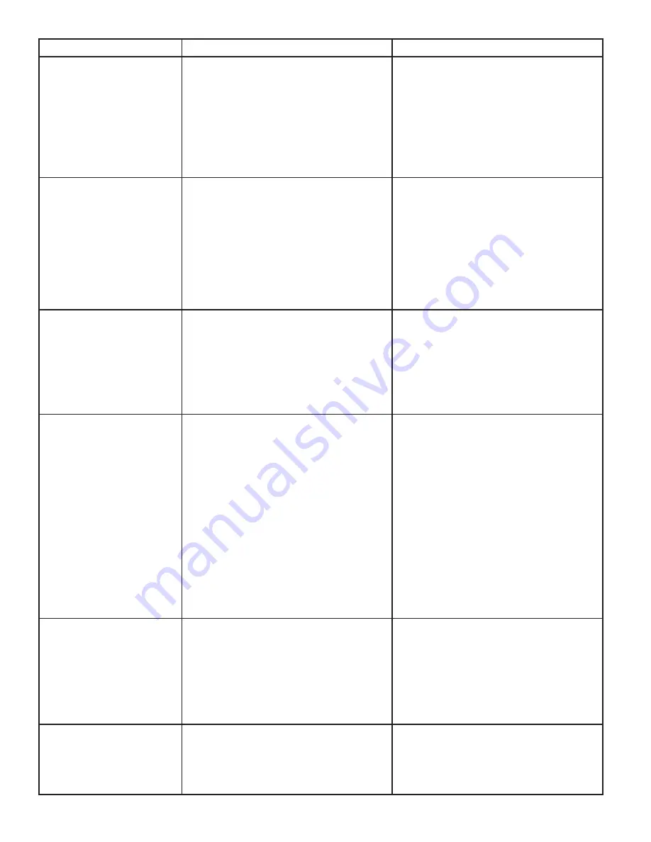
background image

16

TROUBLE

CAUSE

REMEDY

Compressor does not start (no 

hum), but gas cooler fan motor 

runs.

1.  Compressor relay, capacitors, or overload 

protectors malfunctioning.

2. 

Inadequate voltage.

3.  Incorrect wiring.
4.  Compressor malfunctioning.

1.  Replace compressor relay, capacitors, or 

overload protector.

2.  Measure voltage across commom and run 

terminal on compressor. Voltage must not 

drop below 90% of rated voltage.

3.  Refer to wiring diagram and correct.
4. 

Have the unit repaired by a qualified      

service technician.

Compressor does not start but 

hums.

1. 

Inadequate voltage.

2.  Incorrect wiring.
3.  Start capacitor or relay malfunctioning.
4.  Compressor malfunctioning.

1.  Measure voltage across common and run 

terminal on compressor. Voltage must not 

drop below 90% of rated voltage.

2.  Refer to wiring diagram and correct.
3.  Replace start capacitor or relay. Be sure 

to use correct rating. Failure to use correct 

rating will cause compressor failure.

4. 

Have the unit repaired by a qualified     

service technician.

Compressor starts but does not 

switch off start winding (will run 

for only a few seconds before 

internal overload switches 

before internal overload 

switches compressor off).

1. 

Inadequate voltage.

2.  Incorrect wiring.
3.  Starting relay malfunctioning.

1.  Measure voltage across common and run 

terminal on compressor. Voltage must not 

drop below 90% of rated voltage.

2.  Refer to wiring diagram and correct.
3.  Replace starting relay. Be sure to use    

correct relay. Failure to use correct relay 

will cause compressor failure.

Compressor starts and runs 

a short time but shuts off on 

overload.

1.  Dirty condenser.
2. 

Insufficient or blocked air flow.

3. 

Inadequate voltage.

4.  Incorrect wiring.
5.  Defective condenser fan motor.
6.  Refrigerant leak.
7.  Compressor malfunctioning.

1.  Clean the condenser.
2.  Remove all obstruction and allow for 

minimum clearances of 8 inches (203 mm) 

over top. 

3.  Measure voltage across common and run 

terminal on compressor. Voltage must not 

drop below 90% of rated voltage.

4.  Refer to wiring diagram and correct.
5. 

Have the unit repaired by a qualified      

service technician.

6. 

Have the unit repaired by a qualified     

service technician.

7. 

Have the unit repaired by a qualified     

service technician.

Compressor runs normally, but 

water line is frozen.

1.  Low water level in water bath.
2.  Syrup in water bath. 
3.  Water cage is out of position.
4.  Low refrigerant charge or slow refrigerant 

leak.

1.  Add water to water bath until water runs 

out of overflow into drip tray.

2.  Drain water from water bath and refill with 

clean water.

3.  Reposition water cage.

4. 

Have the unit repaired by a qualified     

service technician.

Compressor cycles on and off 

frequently during the initial

pulldown and/or normal

operations.

1.  PCB malfunctioning
2.  Defective probe.
3.  Weak overload or pressure switch.

1.  See page 18.
2.  Replace probe.
3. 

Have the unit repaired by a qualified      

service technician.

Summary of Contents for CED-04

Page 1: ...demark of Lancer 2016 by Lancer all rights reserved 500 Lancer Corporation 6655 Lancer Blvd San Antonio Texas 78219 800 729 1500 Technical Support Warranty 800 729 1550 custserv lancercorp com lancerc...

Page 2: ...s a hazardous situation which if not avoided will result in death or serious injury Be sure to read all Warning statements before proceeding with the installation WARNING Text following the Caution si...

Page 3: ...ualified personnel should service internal components of electrical control housing WARNING Make sure that all water lines are tight and units are dry before making any electrical connections If this...

Page 4: ...59 42 kg ELECTRICAL 115 VAC 60 Hz 5 0 Amps PLAIN WATER SUPPLY Min Flowing Pressure 50 PSIG 0 345 MPA CARBONATED WATER SUPPLY Min Flowing Pressure 25 PSI 0 172 MPA Max Static Pressure 50 PSI 0 345 MPA...

Page 5: ...r PN 82 3401 or MC 163172 Water Regulator recommended CONSIDER THE FOLLOWING BEFORE INSTALLATION Location of Water Supply Lines Location of Drain Location of Electrical Outlet Location of Heating and...

Page 6: ...location that is in close proximity to a properly grounded electrical outlet within five 5 feet 1 5 m of a drain and a water supply that meets the requirements shown in the Specifications section foun...

Page 7: ...sert water line into a large bucket and fill with approx 5 4 gallons 20 4 L of distilled water 9 Add 1 8 oz 4 g of baking soda to distilled water and stir A B C A Bucket B Distilled Water approx 5 4 g...

Page 8: ...l devices on the same outlet WARNING 19 Turn on the power switch at the top of the unit to turn on the unit and begin building an ice bank Installing Remote Syrup Pumps Bag in Box A B C A Syrup Pump B...

Page 9: ...ulk system 2 Connect a 1 4 nut stem and seal to CO2 regulator outlet Then connect tubing routed from tee at syrup pumps tanks A CO2 Regulator B Fitting C Line to CO2 Regulator Manifold D Oetiker Plier...

Page 10: ...oz in 4 sec Use a screwdriver to adjust if needed 3 Remove nozzle by twisting counter clockwise and pulling down then remove diffuser by pulling down 4 Install Lancer yellow syrup separator PN 54 003...

Page 11: ...IZING Lancer equipment new or reconditioned is shipped from the factory cleaned and sanitized in accordance with NSF guidelines The operator of the equipment must provide continuous maintenance as req...

Page 12: ...BIB s 2 Place syrup lines with BIB connectors in a bucket of warm water 3 Activate each valve to fill the lines with warm water and flush out syrup remaining in the lines 4 Prepare Cleaning Solution d...

Page 13: ...flow control 5 Bad syrup pump 1 Adjust CO2 pressure to 80 PSI 0 550 MPA minimum 70 PSI 0 480 MPA for BIB pumps 2 Replace CO2 tank refill 3 Open shutoff fully 4 Remove syrup flow control form upper bo...

Page 14: ...3 Melt ice bank Remove all water Refill Locate possible syrup leak area and repair 4 Reposition water cage 5 Find leak and recharge unit If unit is not frozen 6 Turn water ON and shut unit OFF 7 Turn...

Page 15: ...y 3 Refrigeration system not running 4 Refrigerant leak 5 Gas Cooler fan motor not working 6 Dirty Gas Cooler 7 Dispenser capacity exceeded 1 Check clearances around sides top and inlet of unit Remove...

Page 16: ...w 90 of rated voltage 2 Refer to wiring diagram and correct 3 Replace starting relay Be sure to use correct relay Failure to use correct relay will cause compressor failure Compressor starts and runs...

Page 17: ...upply or adjust CO2 pressure to 70 80 PSI 0 483 0 552 MPA 2 Replace syrup supply 3 Fasten connector tightly 4 Straighten or replace lines 5 Replace BIB pump BIB pump operated but no flow 1 Leak in syr...

Page 18: ...hen back ON again to reset Carbonator timer Again measure continuity of the PCB screw lug connections Terminal 3 to 4 Carbonator During the first 2 5 to 3 5 minutes there should be continuity After 2...

Page 19: ...19 INTENTIONALLY LEFT BLANK...

Page 20: ...20 04 05 06 09 16 18 10 01 02 03 07 08 11 12 13 15 14 17 ILLUSTRATIONS AND PART LISTINGS Main Unit Assembly...

Page 21: ...rup 1 CED 04 48 3551 Tube Assembly Syrup 2 CED 04 48 3550 Tube Assembly Syrup 3 CED 04 48 3572 Tube Assembly Syrup 4 CED 04 09 82 4563 Tank 10 82 0025 01 Leg Set 4 legs w o hardware 11 01 2115 01 Over...

Page 22: ...1553 01 Fan Motor Bracket 03 82 5067 Agitator Assembly 04 30 12717 Agitator Motor Bracket 05 52 3690 Control Housing Assembly 06 25 0047 01 Transformer 07 52 1773 02 EIBC Probe Assembly 08 52 3485 Con...

Page 23: ...23 Wiring Diagram 115 Volt...

Page 24: ...Plumbing Diagram Lancer Corp 800 729 1500 Technical Support Warranty 800 729 1550 custserv lancercorp com lancercorp com...

Reviews: