


Lake Shore Model 340 Temperature Controller User’s Manual
3-8
Installation
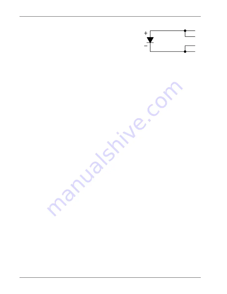
3.4.6 Two-Lead Sensor Measurement
There are times when crowding in a cryogenic system forces users to
read sensors in a two lead configuration because there are not enough
feedthroughs or room for lead wires. If this is the case, plus voltage to
plus current and minus voltage to minus current leads are attached at the
back of the instrument or at the vacuum feedthrough.
The error in a resistive measurement is the resistance of the lead wire
run with current and voltage together. If the leads contribute 2 or 3
Ω
to a 10 k
Ω
reading, the error can
probably be tolerated. When measuring voltage for diode sensors the error in voltage can be calculated as
the lead resistance times the current, typically 10 µA. For example: a 10
Ω
lead resistance times 10 µA
results in a 0.1 mV error in voltage. Given the sensitivity of a silicon diode at 4.2 K the error in temperature
would be only 3 mK. At 77 K the sensitivity of a silicon diode is lower so the error would be close to 50 mK.
Again, this may not be a problem for every user.
3.4.7 Lowering Measurement Noise
Good instrument hardware setup technique is one of the least expensive ways to reduce measurement noise.
The suggestions fall into two categories: (1) Do not let noise from the outside enter into the measurement,
and (2) Let the instrument isolation and other hardware features work to their best advantage.
• Use four lead measurement whenever possible.
• Do not connect sensor leads to chassis or earth ground.
• If sensor leads must be grounded, ground leads on only one sensor.
• Use twisted shielded cable outside the cooling system.
• Attach the shield pin on the sensor connector to the cable shield.
• Do not attach the cable shield at the other end of the cable, not even to ground.
• Run different inputs and outputs in their own shielded cable.
• Use twisted wire inside the cooling system.
• Use similar technique for heater leads.
• Use a grounded receptacle for the instrument power cord.
• Consider ground strapping the instrument chassis to other instruments or computers.
3.5 HEATER OUTPUT SETUP
The following paragraphs cover the heater wiring from the vacuum shroud to the instrument for both control
loop outputs. Software settings and limit configuration of the heater output are detailed in Paragraph 6.12.1.
For information on choosing and installing an appropriate resistive heater, refer to the Paragraph 2.4.
Loop 1 output is discussed in Paragraph 3.5.1. Heater output connector for Loop 1 is discussed in Paragraph
3.5.2. Heater output wiring for Loop 1 is discussed in Paragraph 3.5.3. Heater protection and fuse for loop is
discussed in Paragraph 3.5.4. Noise on Loop 1 heater leads is discussed in Paragraph 3.5.5. The Lake Shore
Model 3003 Heater Output Conditioner is discussed in Paragraph 3.5.6. The Loop 2 output is discussed in
Paragraph 3.5.7. Loop 2 output resistance is discussed in Paragraph 3.5.8. The Loop 2 output connector is
discussed in Paragraph 3.5.9. Loop 2 heater protection is discussed in Paragraph 3.5.10. Finally, boosting the
output power is discussed in Paragraph 3.5.11.
3.5.1 Loop 1 Output
The Model 340 has two control loops. Loop 1 can be considered a primary loop because it is capable of
driving 100 W of heater power. The heater output for Loop 1 is a traditional control output for a cryogenic
temperature controller. It is a variable DC current source with several software settable ranges and limits.
The maximum heater output current is 2 A and maximum compliance voltage is 50 V.
3.5.2 Heater Output Connector for Loop 1
A dual banana jack on the rear panel of the instrument is used for connecting wires to the Loop 1 heater. A
standard dual banana plug mating connector is included in the connector kit shipped with the instrument. This
is a common jack and additional mating connectors can be purchased from local electronic suppliers. They
can also be purchased from Lake Shore (P/N 106-009).
I+
V+
I-
V-
Two-Lead
Diode