Troubleshooting
155
Tailgate Locking Mechanism
N
OTE
:
Refer to the main hydraulic schematic.
The tailgate locking mechanism is equipped with hydraulic safety systems that prevent accidental
unlocking of the tailgate during operation. One of the safety systems is the velocity fuse with the
power bleed
feature; the other is the holding valve.
The spool inside the tailgate section of the valve is designed in such a way as to allow pressure to pass
through it every time pressure is building up in the hydraulic system (that is when the packer is
working). The pressure “burst” goes to the holding valve into port D1 and then out to the cylinder by
port U1 (see Figure 8-9). This will keep the tailgate cylinders pressurized and the tailgate closed
when packing material.
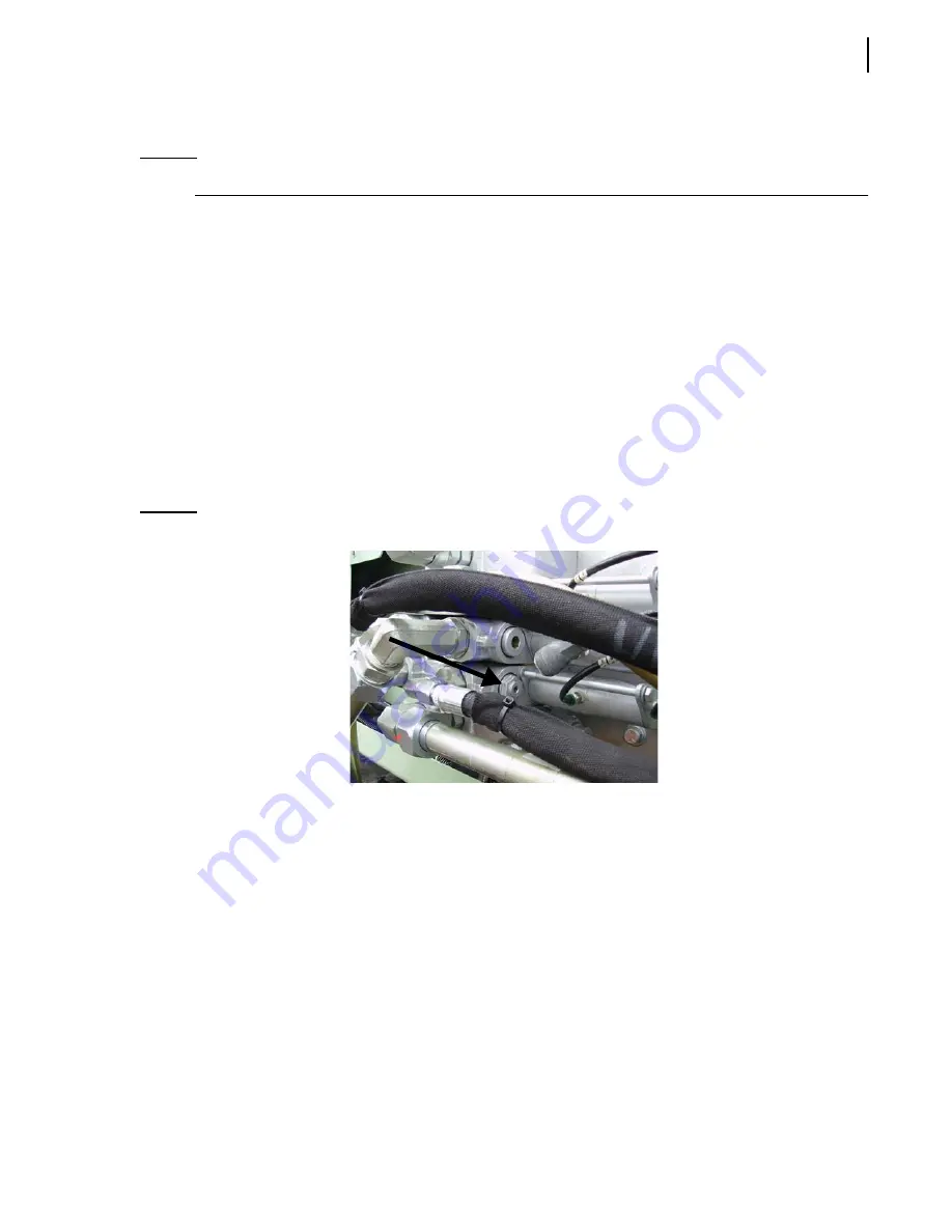
The velocity fuse, located on the right-hand side of the valve, will make sure to drain any slow moving
oil coming from the piston side of the tailgate cylinders. Since the rod side is being pressurized with
the “power bleed” system, the other side has to drain to avoid any pressure build-up. The velocity fuse
makes the piston side open to tank when the oil is moving under 3
gallons per minute, and will shut
close when a flow signal is sent.
Figure 8-8 Velocity fuse
Summary of Contents for Automizer Versa Hand
Page 1: ...AUTOMIZER VERSA HANDTM MAINTENANCE MANUAL...
Page 2: ......
Page 3: ...AUTOMIZER VERSA HAND MAINTENANCE MANUAL...
Page 26: ...18 Safety...
Page 89: ...Lubrication 81 Figure 4 11 Lubrication chart Automizer...
Page 90: ...82 Lubrication Figure 4 12 Lubrication chart Versa Hand arm...
Page 94: ...86 Lubrication Figure 4 18 Cylinder retaining ring Cylinder retaining ring...
Page 95: ...Lubrication 87 Packer Lubrication Points...
Page 96: ...88 Lubrication Hopper Door Hopper door latch Hopper door hinges...
Page 105: ...Hydraulic System 97...
Page 127: ...Hydraulic System 119 Figure 5 29 Detecting cylinder internal leaks 1 2 3 4 5 A A A...
Page 128: ...120 Hydraulic System Main Hydraulic Schematic...
Page 129: ...Hydraulic System 121 Hydraulic Schematic 96 Gallon Gripper...
Page 130: ...122 Hydraulic System Hydraulic Schematic 300 Gallon Gripper...
Page 131: ...Hydraulic System 123...
Page 132: ...124 Hydraulic System...
Page 137: ...Electrical System 129 Electrical Schematics Console 1...
Page 138: ...130 Electrical System Console 2...
Page 139: ...Electrical System 131 Arm Control...
Page 140: ...132 Electrical System Chassis...
Page 141: ...Electrical System 133 Main Body...
Page 142: ...134 Electrical System Hopper...
Page 143: ...Electrical System 135 Arm...
Page 144: ...136 Electrical System...
Page 151: ...Pneumatic System 143 Pneumatic System Schematic...
Page 152: ...144 Pneumatic System...
Page 155: ...Troubleshooting 147 Figure 8 4 Ball end hex wrench metric and SAE...
Page 164: ...156 Troubleshooting Figure 8 9 Tailgate locking mechanism...
Page 166: ...158 Troubleshooting...
Page 189: ...Lifting Arm 181...


