Activity Guide
34
Tech-Design by Lab-Volt
Temperature Control Programming
Controls & Sensors
From the main menu select New. You should have a white sheet with a grid pattern on your screen.
1.
Drag a Start element into your sheet.
2.
Drag an Analog Branch element into the sheet under the Start element until it attaches itself.
3.
Right-click on the Analog Branch element. Under Analog Input, select AX. Under Condition, select
4.
< and enter a value 200 less than the value you recorded for the temperature sensor in your
classroom from the test screen. Leave the y/n pins as they are. Click OK.
Drag a Motor element into the sheet under the Analog Branch element until it attaches itself to the Y
5.
output.
Right-click on this new element and under Motor Output, select M2. Under Image, select Lamp.
6.
Under Action, select OFF. Click OK.
Drag another Motor element into the sheet under the M2 Lamp element until it attaches itself.
7.
Right-click on the element and under Motor Output, select M1. Under Image, select Motor. Under
8.
Action, select CW. Click OK.
Drag an Analog Branch element into the sheet under the M1 Motor element until it attaches itself.
9.
Right-click on the element and under Analog Input, select AX and under Condition, select > and
10.
enter the value for the temperature sensor from the screen test you recorded in your classroom but
add a couple units more to it. Leave the y/n pins as they are. Click OK.
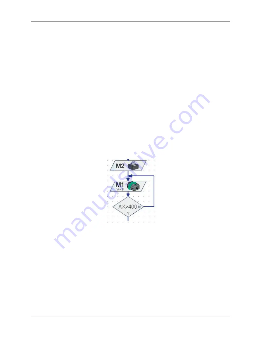
Move the mouse over the N output of this element until the cursor turns to a hand and left click.
11.
Draw a line two grid points to the right and click. Then move up to the middle area of the M2 and
M1 elements and click. Move the line to the left, joining the M2 and M1 elements, and click. See the
graphic below.
Decision Loop
Drag another Motor element into the sheet in line with the M2 Lamp element, 10 grid points to the
12.
right of it.
Right-click on the element. Under Motor Output, select M1. Under Image, select Motor. Under
13.
Action, select Stop. Click OK.
Drag another Motor element into the sheet under the M1 Motor element you just placed until it
14.
attaches itself.
Right-click on the element and under Motor Output, select M2. Under Image, select Lamp. Under
15.
Action, select ON. Click OK.
Move the mouse over the output of this element on the bottom until the cursor turns to a hand and
16.
left click. Draw a line down two grid points and then click. Move the line to the right, approximately
6 spaces, and click again. Now move up to the middle area of the Start and AX elements and click.
Finally, move to the left, joining the Start and AX elements, and click.
Summary of Contents for Tech-Design eSeries
Page 1: ......
Page 2: ......
Page 3: ...Tech Design Controls Sensors Activity Guide eSeries Edition 1 37647 S0 ...
Page 4: ......
Page 8: ...Table of Contents Controls Sensors Activity Guide viii Tech Design by Lab Volt ...
Page 17: ...Activity Guide Tech Design by Lab Volt 9 Controls Sensors Motor Control ...
Page 18: ...Activity Guide 10 Tech Design by Lab Volt Motor Control Controls Sensors ...
Page 21: ...Activity Guide Tech Design by Lab Volt 13 Controls Sensors Hand Dryer ...
Page 22: ...Activity Guide 14 Tech Design by Lab Volt Hand Dryer Controls Sensors ...
Page 25: ...Activity Guide Tech Design by Lab Volt 17 Controls Sensors Sequential Light ...
Page 26: ...Activity Guide 18 Tech Design by Lab Volt Sequential Light Controls Sensors ...
Page 29: ...Activity Guide Tech Design by Lab Volt 21 Controls Sensors Traffic Light ...
Page 30: ...Activity Guide 22 Tech Design by Lab Volt Traffic Light Controls Sensors ...
Page 31: ...Activity Guide Tech Design by Lab Volt 23 Controls Sensors Traffic Light ...
Page 34: ...Activity Guide 26 Tech Design by Lab Volt Sliding Door Controls Sensors ...
Page 35: ...Activity Guide Tech Design by Lab Volt 27 Controls Sensors Sliding Door ...
Page 36: ...Activity Guide 28 Tech Design by Lab Volt Sliding Door Controls Sensors ...
Page 39: ...Activity Guide Tech Design by Lab Volt 31 Controls Sensors Temperature Control ...
Page 40: ...Activity Guide 32 Tech Design by Lab Volt Temperature Control Controls Sensors ...
Page 45: ...Activity Guide Tech Design by Lab Volt 37 Controls Sensors Welding Robot ...
Page 46: ...Activity Guide 38 Tech Design by Lab Volt Welding Robot Controls Sensors ...
Page 47: ...Activity Guide Tech Design by Lab Volt 39 Controls Sensors Welding Robot ...
Page 52: ...Appendix A Safety Activity Guide 44 Tech Design by Lab Volt ...


