LAARS Heating Systems
Page 120
Burner Ignition Sequence
Here is the start-up sequence following a Lead Lag
(LL) Central Heating request:
1. The thermostat used for the LL Central Heat
function calls for heat. On a system set up for
Lead/Lag operation, this will be the System
sensor. (The setpoint or modulation can
also be controlled by an external 4 – 20 mA
control.)
2. The Boiler pump and System pump are
energized. The water temperature in the
System loop drops until it reaches the LL
Central Heat Setpoint minus the LL Central
Heat On Hysteresis value.
3. The controller prepares to start the burner.
The controller does a system check, flap valve
check, and safety chain test. The blower fan is
switched on.
4. The air pressure switch is closed, and the
purge rate proving fan rpm is reached. The
Pre-Purge time starts.
5. When the Purge time is complete, the purge
fan rpm is changed to the Lightoff Rate.
6. When the fan rpm reaches the light-off rpm,
the Pre-Ignition time begins.
7. During the Pre-ignition time, the controller
energizes the igniter and checks for flame.
8. After Pre-ignition, the control enters the
ignition sequence and the gas valve is
energized. The flame signal is compared with
a preset flame threshold value. If the flame
signal is higher than the flame threshold, the
gas valve remains on and the burner is allowed
to continue to the Run phase. If the flame
signal is below the threshold, the controller
returns to the Pre-Purge phase and starts the
ignition process again.
9. The igniter is turned off at the end of the
ignition period.
10. During the Run period, the speed of the
burner fan and the firing rate of the burner(s)
is modulated in response to changes in
demand. (See the next section – “Modulation
Sequence.”)
11. The demand ends when System sensor
temperature equals the Lead/Lag Central Heat
Setpoint plus the Lead/Lag Central Heat Off
Hysteresis value (approx. +10°F).
12. At the end of the Lead/Lag Central Heat
request, the burner is switched off. The fan
stays on until Post Purge is complete.
13. Any new Lead/Lag Central Heat request is
blocked for the Anti Short Cycle time.
14. The Boiler pump and System pump remain on
during their pump overrun times.
15. At the end of the pump overrun times, the
Boiler and System pumps are turned off.
lead/lag modulation Sequence
For a detailed explanation, see Section 9.
Domestic Hot Water Priority
The start-up sequence for a Domestic Hot Water
request, on a system with Domestic Hot Water
priority, is essentially the same as the process we
have just described. The Domestic Hot Water loop
can be considered as just another heating loop on the
system, except the controller can be set to give this
loop priority. The input is supplied by an aquastat,
rather than a thermostat. Circulation in the Domestic
Hot Water loop is provided by a separate pump.
When a Domestic Hot Water demand appears at the
same time as a call for heat by Central Heating, the
priority feature forces the system to switch to the
Domestic Hot Water demand for the priority time.
The Domestic Hot Water priority demand forces the
controller to operate using the DHW setpoint.
For a detailed explanation, see the material on
Domestic Hot Water in Section 9.
Safety Shutdown functions
Each controller has extensive self-checking and
safety features. The controller will shut down the
burner and lock it out under any of the following
conditions:
During the Synchronization Period:
•
Locks out if the Lead/Lag Master cannot
locate any of the boilers, or cannot download
information from any of the controllers.
•
Locks out if the Lead/Lag Master cannot
locate any of the flap valves, or cannot
determine the status of a valve (Open or
Closed).
•
Locks out if a safety-related parameter has
been changed, but the change has not been
verified and the controller has not been reset
using the button on the front of the control.
Summary of Contents for NTV1000
Page 2: ......
Page 35: ...NeoTherm Boilers and Water Heaters Page 31 Fig 20 Ladder Diagram...
Page 36: ...LAARS Heating Systems Page 32 Fig 21 Wiring Diagram...
Page 37: ...NeoTherm Boilers and Water Heaters Page 33...
Page 51: ...NeoTherm Boilers and Water Heaters Page 47 Fig 52 Connection Terminals...
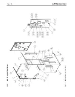
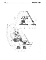
Page 130: ...LAARS Heating Systems Page 126 Fig 140 Machine Frame and Rear Panel 13 3 PARTS ILLUSTRATIONS...
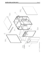
Page 131: ...NeoTherm Boilers and Water Heaters Page 127 Fig 141 Front Panel and Covers...
Page 132: ...LAARS Heating Systems Page 128 Fig 142 Burners and Combustion Chambers...
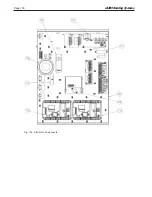
Page 134: ...LAARS Heating Systems Page 130 Fig 145 Electronic Components...
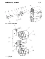
Page 135: ...NeoTherm Boilers and Water Heaters Page 131 Fig 146 Condensate Trap Fig 147 Control Bezel...
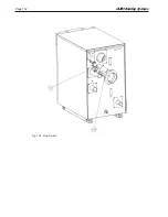
Page 136: ...LAARS Heating Systems Page 132 Fig 148 Flow Switch...
Page 137: ...NeoTherm Boilers and Water Heaters Page 133 This page intentionally left blank...

