NeoTherm Boilers and Water Heaters
Page 79
• Turn off the call for heat, and set both
burners to run at 1200 RPM for low fire. Turn
on the call for heat, and check the performance
again.
19. If the CO
2
doesn’t track between the correct
limits, there is a possibility that one of the
burners has not been set up correctly. If
this occurs, repeat the setup procedure to
confirm that each burner is set up correctly.
If this condition persists, call the factory for
assistance. Before calling, be prepared to
supply the factory with the conditions at the
site where the boiler is installed - for example,
vent lengths, gas supply pressures with all
boilers operating, CO
2
and CO for each burner
individually and together, etc. Be able to
describe the ignition characteristics and the
color of the flame seen through the sight glass
of each burner.
20. When troubleshooting a burner setup, it is
sometimes helpful to watch the pressure
differential between the gas inlet and outlet.
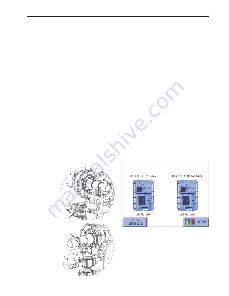
To measure this, install a differential pressure
gauge capable of reading negative 0.01 inches
W.C. (0.002kPa). Attach the gauge to the
positive and negative ports shown in Fig. 106.
When the testing is complete, remove the
pressure gauge, and plug the ports. Repeat the
test setup on each burner.
Job P - Set Date and time on System
Display
(This is a Lead/Lag function – do this once for the whole Lead/
Lag system. Use the controller set up as the Lead/Lag Master –
usually the Primary controller on Boiler 1.)
The display acting as the Lead/Lag Master includes
an internal clock, which keeps track of the date and
time. This setting is important, because all of the
log entries for any Lockouts and Alerts include time
listings. If the Date and Time setting for the Lead/
Lag Master is not correct, the listings in the Lockout
and Alert logs will be incorrect.
The current version of the display does not include a
battery backup. This means that, if the boiler which
includes the display loses power, the Date and Time
setting for the system will be lost. (Any Faults or
Alerts recorded before the boiler lost power will have
the correct date and time listed.)
For this reason, it is important that you set the Date
and Time in two situations:
• When you first set up the Lead/Lag system.
• After each occasion when the power to the
boiler is interrupted.
Here is the procedure:
1. Start at the Home screen.
fig. 107 – Home Screen
fig. 106 – Connections for Pressure Gauge
Positive connection point
Negative connection point
Summary of Contents for NTV1000
Page 2: ......
Page 35: ...NeoTherm Boilers and Water Heaters Page 31 Fig 20 Ladder Diagram...
Page 36: ...LAARS Heating Systems Page 32 Fig 21 Wiring Diagram...
Page 37: ...NeoTherm Boilers and Water Heaters Page 33...
Page 51: ...NeoTherm Boilers and Water Heaters Page 47 Fig 52 Connection Terminals...
Page 130: ...LAARS Heating Systems Page 126 Fig 140 Machine Frame and Rear Panel 13 3 PARTS ILLUSTRATIONS...
Page 131: ...NeoTherm Boilers and Water Heaters Page 127 Fig 141 Front Panel and Covers...
Page 132: ...LAARS Heating Systems Page 128 Fig 142 Burners and Combustion Chambers...
Page 134: ...LAARS Heating Systems Page 130 Fig 145 Electronic Components...
Page 135: ...NeoTherm Boilers and Water Heaters Page 131 Fig 146 Condensate Trap Fig 147 Control Bezel...
Page 136: ...LAARS Heating Systems Page 132 Fig 148 Flow Switch...
Page 137: ...NeoTherm Boilers and Water Heaters Page 133 This page intentionally left blank...


