NeoTherm Boilers and Water Heaters
Page 45
In either kind of installation, a system sensor is
usually used to monitor the demand. The input from
this sensor is used to control the modulation rates of
the operating burners.
Boiler
Burner
Position
Control
Master/Slave As-
signment
Modbus
Control Ad-
dress
1
Upper
Primary
Lead/Lag Master,
also Slave 1
1
1
Lower
Secondary
Slave 2
2
2
Upper
Primary
Slave 3
3
2
Lower
Secondary
Slave 4
4
3
Upper
Primary
Slave 5
5
3
Lower
Secondary
Slave 6
6
4
Upper
Primary
Slave 7
7
4
Lower
Secondary
Slave 8
8
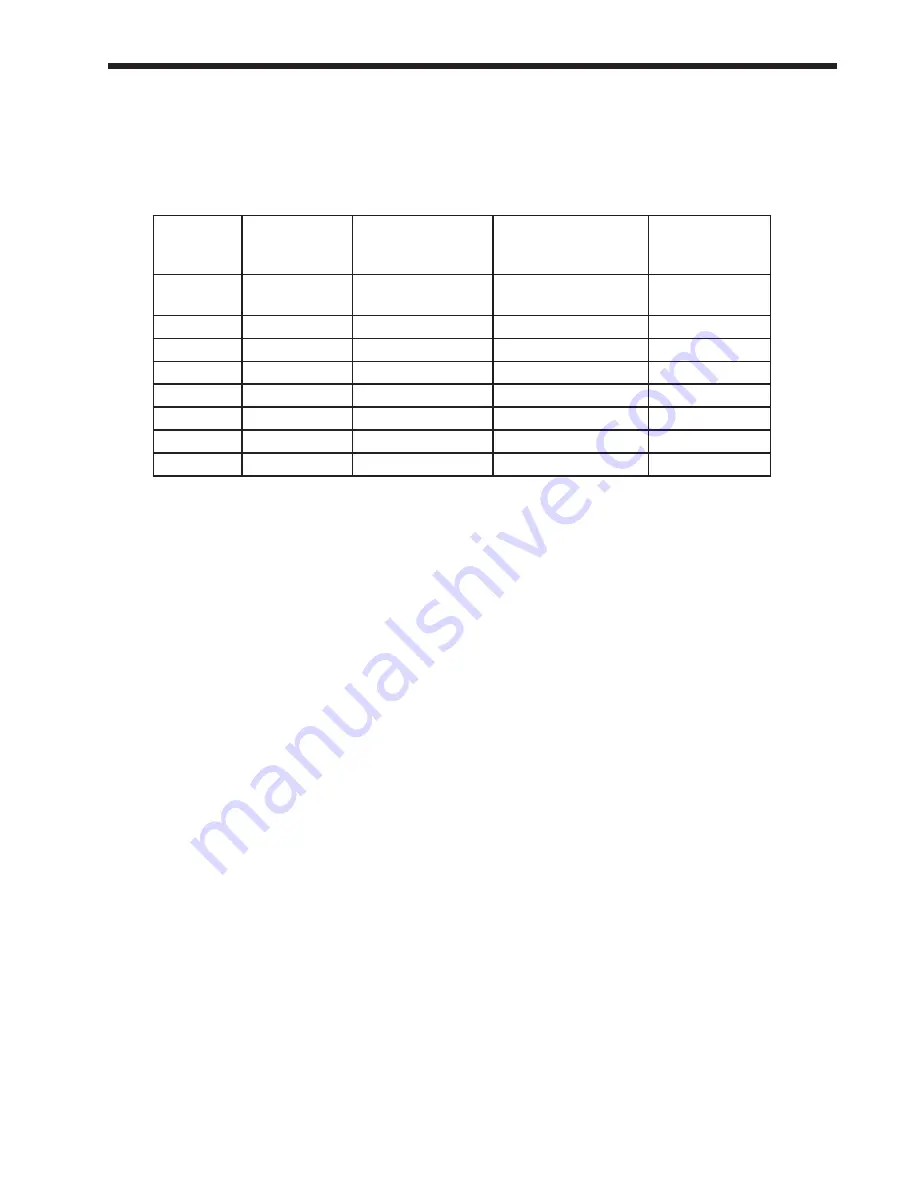
table 11 – master/Slave assignments and modbus Control addresses
9.1.2
lead/lag modulation Cycle
note
- We will explain the modulation cycle here,
in case you need to understand how the Lead/Lag
system actually operates. If you are just installing
the unit(s) and want to skip this section, just
remember that, as the heating demand increases,
the Lead/Lag system puts more burners on-line.
As the heating demand is reduced, the Lead/Lag
system shuts off some of the burners.
A Run sequence is initiated when the system
temperature falls to the setpoint less the On
Hysteresis value. The default setting for On
Hysteresis is -5°F, but this is adjustable. The
setpoint used to initiate the Run sequence is the
Lead/Lag Central Heat setpoint.)
The Lead/Lag controller decides which burner is
assigned to start first. This assignment is rotated
across all of the available burners so that any one
burner does not run significantly longer than the
others. The Lead/Lag controller tracks the run
times for all of the available burners, and uses this
to calculate the starting order for the burners. This
means that each time the system starts up, a different
burner may start first. It also means that the Primary
burner on a particular boiler may start first one time,
and the Secondary burner for that boiler may start
first the next time.
When the Run sequence is initiated, the burner with
the least amount of runtime will fire. If the heating
demand increases so that the firing rate of that first
burner rises to 65% fan speed (the Base Load value),
the next burner in the sequence will start up and
begin firing at 35% fan speed. After this, both of the
active burners will modulate up or down together, in
reaction to the changes in demand. See Fig. 51.
If the system loop temperature rises above
the LL CH setpoint, then the two burners will
simultaneously drop their fan speeds. If both boilers
drop to their minimum fan speeds (29%), then the
second burner will drop out.
If the heating demand continues to increase, and
the system loop temperature continues to drop,
then the two burners will increase their fan speeds
together. When they reach 65%, the next burner in
the sequence will start up and be added to the group.
All three boilers will continue to fire simultaneously
at equal input rates.
If the modulation rate for all three burners drops
to the minimum fan speed (29%), the last burner
started will drop out. If the demand continues to
drop, the second burner started will also drop out.
If the system temperature reaches the LL CH
setpoint value plus the Off Hysteresis figure, all of
the burners will shut off. (The default setting for Off
Hysteresis is +5°F, but this is adjustable.)
If any of the boilers approaches its high limit
temperature, that boiler will modulate back to stay
below the high limit.
As the heating demand continues to change, the
Lead/Lag Master will continue to add, remove, or
modulate the additional boilers in the system.
Let’s consider the following example:
Four NeoTherm boilers are tied together via Modbus
connections. Here are the Master/Slave assignments
and the Modbus control addresses:
Summary of Contents for NTV1000
Page 2: ......
Page 35: ...NeoTherm Boilers and Water Heaters Page 31 Fig 20 Ladder Diagram...
Page 36: ...LAARS Heating Systems Page 32 Fig 21 Wiring Diagram...
Page 37: ...NeoTherm Boilers and Water Heaters Page 33...
Page 51: ...NeoTherm Boilers and Water Heaters Page 47 Fig 52 Connection Terminals...
Page 130: ...LAARS Heating Systems Page 126 Fig 140 Machine Frame and Rear Panel 13 3 PARTS ILLUSTRATIONS...
Page 131: ...NeoTherm Boilers and Water Heaters Page 127 Fig 141 Front Panel and Covers...
Page 132: ...LAARS Heating Systems Page 128 Fig 142 Burners and Combustion Chambers...
Page 134: ...LAARS Heating Systems Page 130 Fig 145 Electronic Components...
Page 135: ...NeoTherm Boilers and Water Heaters Page 131 Fig 146 Condensate Trap Fig 147 Control Bezel...
Page 136: ...LAARS Heating Systems Page 132 Fig 148 Flow Switch...
Page 137: ...NeoTherm Boilers and Water Heaters Page 133 This page intentionally left blank...


