LAARS Heating Systems
Page 2
Operator
interface
Boiler 1
Slave 4
Boiler 2
Slave 3
Slave 2
Lead Lag
Master and
Slave 1
Slave 6
Boiler 3
Slave 5
Slave 8
Boiler 4
Slave 7
Addr
1
Addr
2
Addr
3
Addr
4
Addr
5
Addr
6
Addr
7
Addr
8
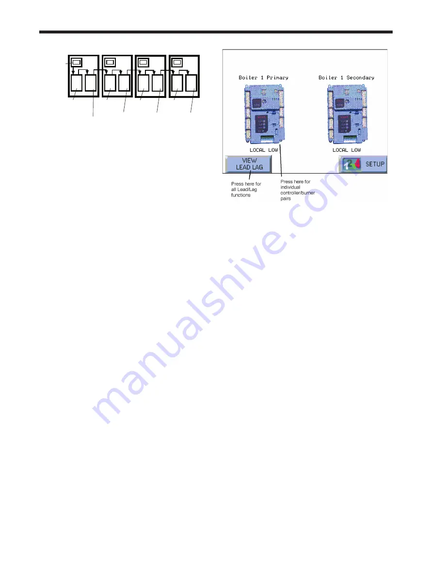
fig. 2 – lead/lag arrangement in a multiple-
Boiler Installation
In a multiple-boiler installation, just one of the
operator interfaces is active. It can communicate
with all of the controller/burner pairs in the system,
so it displays information from all of the burners. A
single system sensor provides the control input for
the system.
Actually, even a NeoTherm 1000 unit set up as a
single boiler still uses Lead/Lag operation. If the
heating load becomes too great for the first burner,
the control system automatically starts the second
burner.
To work with this control system, you will need
to understand the difference between two kinds of
control functions:
•
Some of the functions control all of the
controller/burner pairs, working together as
part of the Lead/Lag system. As an example,
the setpoint for a whole multiple-boiler system
is set by a single value: “Central Heat Lead/
Lag Setpoint.” By changing this one value,
you change the setpoint used by the whole
system. The action of all of the controller/
burner pairs will refer back to that single value.
On the Operator Interface, from the Home
screen you can reach all of the Lead/Lag
functions by pressing the View Lead Lag
button. See Fig. 3.
•
Other functions apply only to each separate
controller/burner pair. As an example, each
controller/burner has a name, and this can be
changed.
The Home screen on the Operator Interface
will show icons for each of the controller/
burner pairs connected to the system. To
reach one of the functions for an individual
controller/burner, press the icon for that
controller/burner. On the following screen,
press the Configure button. This will take
you to all of the configuration options for that
individual controller/burner.
fig. 3 – Going to lead/lag and Individual
functions
note
– For individual functions, if you want to make
a change on all of the controller/burner pairs in the
system, you will have to go to each controller/burner
separately and repeat the change for each of them.
If there are eight controller/burners in the system,
and you want to make the same change on all of
them, go to each of the eight controller/burner pairs
separately.
As we go through the explanations in this manual,
we will point out whether a control function affects
the whole Lead/Lag system, or just an individual
controller/burner pair.
This has been just a quick introduction, but this
manual includes two longer sections that will help
you to work with the control system:
•
Section 8 – “Using the Controls on the
NeoTherm 1000”
This is an introduction to the Operator
Interface. It explains how to “get along” with
the interface: how to move through the various
screens, enter and change values, and so on.
•
Section 9 – “Setup and Configuration”
The first part of this section includes a more
complete explanation of the Lead/Lag system.
The rest of the section includes detailed setup
instructions.
If you are not familiar with the control system, the
installation and setup process will go much more
smoothly if you read through these three sections
before beginning work.
Summary of Contents for NTV1000
Page 2: ......
Page 35: ...NeoTherm Boilers and Water Heaters Page 31 Fig 20 Ladder Diagram...
Page 36: ...LAARS Heating Systems Page 32 Fig 21 Wiring Diagram...
Page 37: ...NeoTherm Boilers and Water Heaters Page 33...
Page 51: ...NeoTherm Boilers and Water Heaters Page 47 Fig 52 Connection Terminals...
Page 130: ...LAARS Heating Systems Page 126 Fig 140 Machine Frame and Rear Panel 13 3 PARTS ILLUSTRATIONS...
Page 131: ...NeoTherm Boilers and Water Heaters Page 127 Fig 141 Front Panel and Covers...
Page 132: ...LAARS Heating Systems Page 128 Fig 142 Burners and Combustion Chambers...
Page 134: ...LAARS Heating Systems Page 130 Fig 145 Electronic Components...
Page 135: ...NeoTherm Boilers and Water Heaters Page 131 Fig 146 Condensate Trap Fig 147 Control Bezel...
Page 136: ...LAARS Heating Systems Page 132 Fig 148 Flow Switch...
Page 137: ...NeoTherm Boilers and Water Heaters Page 133 This page intentionally left blank...


