background image

 Termo 

ISOTTA – DSA 

20 


7199701 Rev.05 – EN


2. 

TECHNICAL DESCRIPTION  

La  Nordica  thermoheating  stoves  are  suitable for  heating  homes  using  a  centralised  heating  system made  up  from 
radiators  or  heat  convectors  entirely  or  partially  replacing  the  traditional  gas  or  diesel  oil  boiler.  They  are  ideal  for 
holiday apartments and week-end homes or as auxiliary heating throughout the entire year.  
Wooden logs are used ad fuel. 
The fireplace is found inside the boiler, is built in 4 mm thick steel and is reinforced using welded nails. The water in 
the heating system circulates in the boiler, which absorbs the heat produced in the fireplace. 
A swivelling, removable grid is found inside the fireplace. 
The  hearth is  equipped  with  a  panoramic  door  with  ceramic  glass  (resistant  up  to  700  °C). This  allows  a  wonderful 
view on the burning flames and avoids any possible output of sparks and smoke. 
The heating of the environment is made: 

a)  radiation:  the  heat  is  radiated  into  the  environment  through  the  panoramic  window  and  the  hot  external 

surfaces of the thermoheating stove;


b)  by  conduction:  radiators  or  heat  convectors  of  the  centralised  system  fed  by  hot  water  produced  by  the 

thermoheating stove itself.


The thermoheating stove has regulators for primary and secondary air, with which the combustion air is adjusted. 

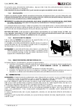
PRIMARY air control 
With the primary air control (Picture 1 

A) is adjusted the passage of 

air  through  the  ash  drawer  and  the  grate  in  the fuel  direction. The 
primary  air  is  necessary  for  the  combustion  process.  The  ash 
drawer must be regularly emptied, so that the ash does not obstruct 
the  primary  air  entry.  Through  the  primary  air  the  fire  is  also  kept 
alive. 
During  wood  combustion,  the  register  of  primary  air  must  be 
opened  only  for  a  while,  because  otherwise  the  wood  burns  fast 
and the stove may overheat. For the correct arrangement, see the 
table on chapter 10. 

SECONDARY air control 


Over  the  door  of  the  hearth  there  is  the  secondary  air  control 
(Picture  1 

B).  This  regulator  must  be  open  (the  lever  must  be 

moved  to  the  right),  especially  for  wood  combustion,  so  that  un-
burnt carbon does not undergo a post-combustion. See chapter 10. 
Through this register it is possible to adjust the power of the stove. 
Leaving  it  slightly  open,  according  to  the  flue  of  the  chimney,  it  is 
possible to keep the glass clean. 

3. 

RULES FOR INSTALLATION  

Installation of the thermo stove and auxiliary equipment in relation to the heating system must comply with all current 
Standards and Regulations and to those envisioned by the law.  
Installation relating to the connections of the system, commissioning and the check of the correct functioning must be 
carried  out  in  compliance  with  the  regulations  in  force  by  authorised  professional  personnel  with  the  requisites 
required  by  the  law,  being  national,  regional,  provincial  or  town  council  present  in  the  country  within  which  the 
appliance is installed, besides these present instructions. 
Installation  must  be  carried  out  by  authorised  personnel  who  must  provide  the  buyer  with  a  system  declaration  of 
conformity  certificate  and  will  assume  full  responsibility  for  final  installation  and  as  a  consequence  the  correct 
functioning of the installed product. 
NORDICA S.p.A. cannot be held responsible for lack of respect for such precautions.  
Before installation, accurately wash the pipes of the system in order to remove any residuals that could compromise 
the correct functioning of the appliance. 
 
IMPORTANT: 

a)  In case of water leaking, close the water supply and promptly warn the after sales technical service; 
b)  The system working pressure must periodically be checked. 
c)  If  not  using  the  boiler  for  a  long  period  of  time,  it  is  recommended  that  the  after  sales  technical  service  is 

contacted to carry out at least the following operations: 

close the water taps of both the thermal system and the domestic hot water system; 

empty the thermal system and the domestic hot water system if there is risk of freezing. 

 
La  Nordica  S.p.a.  declines  all  responsibility  for  damage  to  objects  and/or  injury  to  persons  caused  by  the 
system.  Moreover,  it  is  not liable  for  the  product  that  has  been  modified without  authorisation  and also  for 
the use of non-original spare parts 


Picture 1 

A

Flat grate 

Summary of Contents for Termo Isotta DSA

Page 1: ...TION USE AND MAINTENANCE EN ANWEISUNGEN FÜR DIE AUFSTELLUNG DEN GEBRAUCH UND DIE WARTUNG DE INSTRUCTIONS POUR L INSTALLATION L UTILISATION ET L ENTRETIEN FR NORME DI SICUREZZA SUGLI APPARECCHI Secondo le norme di sicurezza sugli apparecchi l acquirente e l esercente sono obbligati ad informarsi sul corretto funzionamento in base alle istruzioni per l uso SAFETY PRESCRIPTIONS ON EQUIPMENT According...

Page 2: ...Termo ISOTTA DSA 2 7199701 Rev 05 IT EN DE FR ...

Page 3: ...s we produce the materials which will get in touch with food are suitable for alimentary use according to the a m CE regulation KONFORMITÄTSERKLÄRUNG DES HERSTELLERS Betreff Fehlen von Asbest und Kadmium Wir bestätigen dass die verwendeten Materialen oder Teilen für die Herstellung der La Nordica Geräte ohne Asbest und Derivat sind und auch das Lot für das Schweißen immer ohne Kadmium ist Betreff ...

Page 4: ...FLECTEUR FUMÉE 58 17 SCHEDA TECNICA TECHNICAL DATA SHEETS TECHNISCHE PROTOKOLLE FICHE TECHNIQUE 59 18 SCHEMA D INSTALLAZIONE INSTALLATION DIAGRAM INSTALLATION SCHEME 60 INDEX EN 1 TECHNICAL DATA 19 2 TECHNICAL DESCRIPTION 20 3 RULES FOR INSTALLATION 20 3 1 OPEN expansion VESSEL system 21 3 2 CLOSED expansion VESSEL system 22 3 3 AUTOMATIC THERMOSTATIC MIXER VALVE OPTIONAL 22 3 4 HEAT DISCHARGE VAL...

Page 5: ... INSTALLAZIONE INSTALLATION DIAGRAM INSTALLATION SCHEME 60 SOMMAIRE FR 1 DONNES TECHNIQUES 45 2 DESCRIPTION TECHNIQUE 46 3 NORMES POUR L INSTALLATION 46 3 1 Vase d expansion OUVERT 47 3 2 Vase d expansion FERME 48 3 3 VANNE MELANGEUSE THERMOSTATIQUE AUTOMATIQUE OPTIONNEL 48 3 4 VANNE DE DECHARGE THERMIQUE OPTIONNEL 49 4 SECURITE ANTINCENDIE 49 4 1 INTERVENTION EN CAS D URGENCE 50 5 CONDUIT DE FUME...

Page 6: ...VEA1 5 VEC3 Dimensioni apertura focolare in mm L x H 519 x 340 Dimensioni corpo focolare testata focolare in mm L x H x P 570 x 300 x 325 Dimensioni forno in mm L x H x P Tipo di griglia Griglia piana girevole dall esterno Altezza termostufa in mm 775 Larghezza termostufa in mm 760 Profondità termostufa con maniglie in mm 520 Peso in Kg 212 Distanze di sicurezza antincendio Capitolo 4 Diametro 200...

Page 7: ...e aperto quindi la leva deve essere spostata verso destra in particolare per la combustione di legna in modo che il carbonio incombusto possa subire una post combustione Vedi paragrafo 10 Attraverso questo registro è possibile regolare la potenza di riscaldamento della stufa Lasciandolo leggermente aperto a seconda del tiraggio del camino è possibile mantenere il vetro pulito 3 NORME PER L INSTALL...

Page 8: ...o di espansione aperto fra il tubo di sicurezza ed il tubo di carico Questa provocherebbe l ossigenazione dell acqua e la conseguente corrosione del termoprodotto e dell impianto in tempi molto brevi 4 VALVOLA DI SCARICO TERMICO costituisce una ulteriore sicurezza positiva in grado di prevenire l ebollizione anche in assenza di energia elettrica E costituita da un corpo valvola simile ad una valvo...

Page 9: ...e tale da garantire che non venga superata la temperatura limite imposta dalla norma Il collegamento tra il gruppo di alimentazione e la valvola deve essere privo di intercettazioni La pressione a monte del circuito di raffreddamento deve essere di almeno 1 5 bar 3 3 Valvola miscelatrice Termostatica Automatica OPTIONAL La valvola miscelatrice termostatica automatica trova applicazione nei generat...

Page 10: ...cati b davanti alla stufa camino non deve esserci alcun oggetto o materiale di costruzione infiammabile e sensibile al calore a meno di 100 cm di distanza Tale distanza può essere ridotta a 40 cm qualora venga installata una protezione retroventilata e resistente al calore davanti all intero componente da proteggere c qualora il prodotto venga installato su un pavimento di materiale infiammabile b...

Page 11: ...ttare i dati tecnici del manuale di istruzioni Qualora le canne fumarie fossero a sezione quadrata o rettangolare gli spigoli interni devono essere arrotondati con raggio non inferiore a 20 mm Per la sezione rettangolare il rapporto massimo tra i lati deve essere 1 5 Una sezione troppo piccola provoca una diminuzione del tiraggio Si consiglia un altezza minima di 4 m Sono vietate e pertanto pregiu...

Page 12: ...e di qualsiasi corpo estraneo essere facilmente ispezionabile per eventuali operazioni di manutenzione e pulizia Fig 6 Fig 7 Figura 8 Figura 9 1 Comignolo industriale ad elementi prefabbricati consente un ottimo smaltimento dei fumi 2 Comignolo artigianale La giusta sezione di uscita deve essere minimo 2 volte la sezione interna della canna fumaria ideale 2 5 volte 3 Comignolo per canna fumaria in...

Page 13: ...l installazione di un regolatore di tiraggio supplementare valvola a farfalla sul tubo di scarico o nel camino 7 AFFLUSSO D ARIA NEL LUOGO D INSTALLAZIONE DURANTE LA COMBUSTIONE Poiché le stufe ricavano la loro aria di combustione dal locale di installazione è OBBLIGATORIO che nel luogo stesso venga immessa una sufficiente quantità d aria In caso di finestre e porte a tenuta stagna es case costrui...

Page 14: ...ioppo 470 4 1 Larice 660 4 4 Abete rosso 450 4 5 Pino silvestre 550 4 4 LEGNI RESINOSI POCO ADATTI PER UNA STUFA Tra gli altri non possono essere bruciati resti di carbone ritagli cascami di corteccia e pannelli legna umida o trattata con vernici materiali di plastica in tal caso decade la garanzia sull apparecchio Carta e cartone devono essere utilizzati solo per l accensione La combustione di ri...

Page 15: ...re regolare l aria per la combustione secondo le indicazioni del paragrafo 10 Durante questa fase non lasciare mai il focolare senza supervisione Non accendere mai l apparecchio quando ci sono gas combustibili nella stanza ATTENZIONE durante le prime accensioni potrà avvenire una consistente condensazione dei fumi con una piccola fuoriuscita d acqua dalla termostufa questo è un fenomeno destinato ...

Page 16: ...ei disturbi alla canna fumaria che fanno si che i gas combusti non vengono aspirati completamente I gas di scarico non fuoriescono più completamente odore intenso di gas In tal caso scuotete più frequentemente la griglia e aumentate l aria per la combustione Caricate in seguito una quantità ridotta di combustibile facendo sì che questo bruci più rapidamente con sviluppo di fiamme e si stabilizzi c...

Page 17: ...to di un coperchio stagno Il recipiente va posto su di un pavimento ignifugo lontano da materiali infiammabili fino allo spegnimento e raffreddamento completo 13 4 MANUTENZIONE DELL IMPIANTO IDRAULICO Ad impianto spento una volta all anno eseguire le seguenti verifiche controllare la funzionalità e l efficienza delle valvole di scarico termico e di sicurezza Qualora queste fossero difettose contat...

Page 18: ...lmente il tiraggio della canna fumaria che dovrà essere eventualmente compensata innalzandola adeguatamente la Normativa UNI 10683 2005 ITALIA prevede che le curve o variazioni di direzione non devono in nessun caso essere superiori a 2 compresa l immissione in canna fumaria Volendo usare la canna fumaria di un caminetto o focolare aperto sarà necessario chiudere ermeticamente la cappa al di sotto...

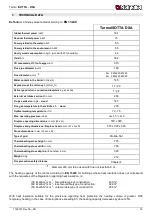
Page 19: ... VEA1 5 VEC3 Fireplace opening dimensions in mm W x H 519 x 340 Fireplace body dimensions fireplace head in mm W x H x D 570 x 300 x 325 Stove dimensions in mm W x H x D Type of grid Mobile flat Thermoheating stove height in mm 775 Thermoheating stove width in mm 760 Thermoheating stove depth with handles in mm 520 Weight in Kg 212 Fire precaution safety distance Chapter 4 Diameter 200 mm to be us...

Page 20: ...t be moved to the right especially for wood combustion so that un burnt carbon does not undergo a post combustion See chapter 10 Through this register it is possible to adjust the power of the stove Leaving it slightly open according to the flue of the chimney it is possible to keep the glass clean 3 RULES FOR INSTALLATION Installation of the thermo stove and auxiliary equipment in relation to the...

Page 21: ...nsion tank between the safety and loading pipe This would cause the water oxygenation and the consequent corrosion of thermo product and installation in a very short time 4 THERMAL DISCHARGE VALVE which is a further positive safety that prevents the boiling even when electric energy is missing It is made by a valve cover like a pressure safety valve which differs from it as it opens by reaching a ...

Page 22: ...upply unit and the valve must be free from interceptions Cooling circuit upstream pressure must be at least 1 5 bar 3 3 AUTOMATIC THERMOSTATIC MIXER VALVE OPTIONAL The automatic thermostatic mixer valve finds applications in solid fuel heat generators as it prevents cold water return in the exchanger Routes 1 and 3 are always open and along with the pump installed on the return Picture 2 R the gua...

Page 23: ...e a steel platform dimensions according to the local regulations The base must extend at least 50 cm at the front and at least 30 cm at the sides in addition to the opening of the loading door Picture 4 B d flammable components e g wall units must be present above the product The chimney stove must operate exclusively with the ash drawer inserted The solid residue of the combustion ashes must be c...

Page 24: ...ion must be 4 dm 2 for example 20 x 20 cm for appliances whose duct diameter is lower than 200 mm or 6 25 dm2 for example 25 x 25 cm for appliances with diameter greater than 200 mm The draught created by the flue must be sufficient but not excessive A too big flue section can feature a too big volume to be heated and consequently cause difficulties in the operation of the appliance to avoid this ...

Page 25: ...ey cap must be higher than the other one of at least 50 cm in order to avoid pressure transfers between the flues themselves 1 Industrial chimney cap with pre fabricated elements it allows an excellent discharge of the smokes 2 Handicraft chimney cap The right output section must be at least twice as big as the internal section of the flue ideal value 2 5 times 3 Chimney cap for steel flue with co...

Page 26: ... of the equipment it is essential that in the installation place it is introduced sufficient air for combustion This means that through suitable openings air must recirculate for the combustion even with doors and windows closed see chapter 7 The depression on the chimney CHIMNEY EFFECT must be 17 20 Pa 1 7 2 mm of water column The measurement must be done always with the equipment hot rating calo...

Page 27: ...e the warranty on the equipment expires Paper and carton must be used only for ignition The combustion of wastes is FORBIDDEN and may damage the stove and the chimney causing health damages and claims by the neighbourhood owing to the bad smell The wood is not a fuel which allows a continuous operation of the appliance as consequence the heating all over the night is not possible ATTENTION the con...

Page 28: ...d however result persistent the flue chimney effect must be checked The thermoheating stove must never be overloaded Too much fuel and too much air for combustion can cause overheating and therefore damage the thermoheating stove Damage caused by overheating is not covered by the warranty 10 NORMAL OPERATION ATTENTION For no reason must the fire be ignited before the system has been completely fil...

Page 29: ...rmoheating stove is in function the circulation pump must be in function in order to dispose of the heat given to the boiler water on the radiators The system must be kept constantly full of water even in period when use of the thermoheating stove is not requested During the winter inactivity must be faced with the addition of antifreeze 13 MAINTENANCE AND CARE Let the installation of your stove t...

Page 30: ... of the safety pipe 14 SUMMER STOP ATTENTION The system must be kept constantly full of water even during the periods when the use of the thermoheating stove is not requested During the winter inactivity must be faced with the addition of antifreeze After you have cleaned the hearth the chimney and the flue trying to eliminate completely the ash and others residuals you must close the doors of the...

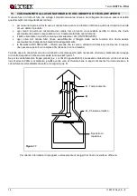
Page 31: ...ary to duct it with a stainless steel tube of at least 200 mm of diameter pos B taking care to close the space between the tube itself and the flue immediately below the chimney cap pos C For further information please contact your Dealer Picture 11 C Plugging A Hermetic closure Inspection hatch B ...

Page 32: ...rbeitstdruck in bar VEA1 5 VEC3 Ausmaße Feuerraumöffnung in mm B x H 519 x 340 Ausmaße Feuerraumkörper Feuerraumfront in mm B x H x T 570 x 300 x 325 Ausmaße Backofen in mm B x H x T Rosttyp Planrost von außen abrüttelbar Höhe Heizungsherd in mm 775 Breite Heizungsherd in mm 760 Tiefe Heizungsherd mit Handgriffen in mm 520 Gewicht in Kg 212 Sicherheitsabstände zur Brandverhütung siehe Kapitel 4 Du...

Page 33: ...chnell verbrennt und der Kaminofen sich überhitzen kann Für die richtige Einstellung bitte siehe Abschnitt 10 Der SEKUNDÄRLUFTSCHIEBER Oberhalb der Feuerraumtür befindet sich ein Sekundärluft Schieber ABB 1 B Dieser Schieber muß ebenfalls bei der Verfeuerung von Holz geöffnet werden also nach rechts geschoben werden damit der unverbrannte Kohlenstoff nachverbrannt werden kann Vgl Abschnitt 10 Durc...

Page 34: ...h in Räumlichkeiten befinden die Frostgeschützt sind das es bei Frost zum Bruch oder sogar zur Explosion des Heizkessels kommen könnte Bei Frostgefahr sollte man dem Wasser der Anlage einen angemessenen Prozentsatz Frostschutzmittel zufügen damit man das Problem ausschließen kann Keinesfalls darf Wasser in das offene Expansiongefäß zwischen dem Sicherheitsrohr und dem Laderohr zirkulieren Hierbei ...

Page 35: ...tungen an der Zuleitung der Heizgeräte in einem Abstand von höchstens 1 m von diesem installieren Die Heizgeräte für den Hausgebrauch müssen VERPFLICHTEND in eine Heizanlage mit GESCHLOSSENEM GEFÄSS installiert werden und einen schon werkseitig vorgesehenen Kühlkreislauf umfassen der mittels eines Sicherheits Thermoventils siehe Kapitel 3 4 zu aktivieren ist und keine Hilfsenergie erfordert Es mus...

Page 36: ...ie folgenden Brandschutzvorschriften beachtet werden a Um eine ausreichende Wärmedämmung zu gewährleisten muss die Mindestanforderungen für Sicherheitsabstand ABB 4 A eingehalten werden Alle Sicherheitsabstände sind auf der Typenschild des Produktes gezeigt und sollten nicht unter der angegebenen Werte liegen b Vor dem Kaminofen dürfen sich keine entzündlichen oder wärmeempfindlichen Gegenstände o...

Page 37: ...ut sein welche gegen die Wärme die Verbrennungsprodukte und etwaige Kondensaten resistent sind Es muss keine Querschnittreduzierung aufweisen und muss einen senkrechten Lauf mit Biegungen nicht höher als 45 haben Wenn es schon benutzt worden ist muss es sauber sein Die technischen Angaben des Gebrauchshandbuches beachten Sollten die Schornsteinrohre einen viereckigen oder rechteckigen Querschnitt ...

Page 38: ...ausgezeichnet 2 Schornsteinrohr aus feuerfestem Material mit doppelter isolierter Kammer und Außenverkleidung aus Halbdichtbeton Wirkungsgrad 100 ausgezeichnet 3 Traditionelles Schornsteinrohr aus Ton viereckiger Querschnitt mit Spalten Wirkungsgrad 80 ausgezeichnet 4 Schornsteinrohre mit rechteckigem Innenquerschnitt dessen Verhältnis von der Zeichnung abweicht sind zu vermeiden Wirkungsgrad 40 A...

Page 39: ...urz wie möglich sein und die Verbindungen der einzelnen Abgasrohre müssen gasdicht sein Der Anschluss an den Schornstein muß mit stabilen und festen Rohren durchgeführt werden wir empfehlen eine Dicke von 2 mm Das Rauchgasrohr muß dicht mit dem Schornstein verbunden sein Der Innendurchmesser des Verbindungsrohres muß dem Außendurchmesser des Rauchgasstutzen entsprechen Dies ist bei Rauchgasrohren ...

Page 40: ...gativ beeinflussen bis hin zum Rauchaustritt in die Wohnräume trotz geschlossener Feuerraumtür Daher dürfen sie unter keinen Umständen gleichzeitig mit dem Ofen betrieben werden Der Unterdruck einer Abzugshaube kann im schlimmsten Falle die Rauchentwicklungen verschlucken mit schweren Folgen für die Ofenbetreiber 8 ZULÄSSIGE UNZULÄSSIGE BRENNSTOFFE Die zulässigen Brennstoffe sind Brennholzscheite ...

Page 41: ...eitung angegebenen Menge und lassen Sie den Ofen mindestens 6 10 Stunden ständig bei Reglern laufen die weniger offen als in der Bedienungsanleitung beschrieben sind 3 Wiederholen Sie diesen Vorgang nach Möglichkeit mindestens 4 5 Mal 4 Befüllen Sie den Ofen danach immer stärker wobei jedoch die Hinweise der Bedienungsanleitung über die maximale Befüllung zu beachten sind und lassen Sie ihn lange ...

Page 42: ...ßere Sekundärluftmenge ist erforderlich BRENNSTOFF Primärluftschieber A Sekundärluft B Holz ZU AUF Stündliche Lademenge kg h 4 4 11 STROMAUSFALL Im Falle eines plötzlichen Stromausfalls während des normalen Betriebs der Anlage sind die folgenden einfachen Handgriffe vorzunehmen um zu vermeiden dass der Thermoofen infolge des fehlenden Pumpenbetriebs zum Sieden kommt 1 Die Primär und Sekundärluftre...

Page 43: ...doch nicht um einen Fehler des Ofens WICHTIG Die Reinigung des Sichtfensters darf nur bei kaltem Ofen erfolgen um eine Explosion der Scheibe zu vermeiden Keine Tücher und scheuernde oder chemisch aggressive Mittel verwenden Das richtige Anfeuern die Verwendung der geeigneten Art und Menge an Brennstoff die korrekte Einstellung des Sekundärluftreglers der ausreichende Kaminzug und das Vorhandensein...

Page 44: ...ndert erhalten bleiben soll 15 ANSCHLUSS AN DEN RAUCHABZUG EINES OFFENEN KAMINS Der Rauchkanal ist der Rohrabschnitt der das Produkt mit dem Rauchabzug verbindet Bei der Verbindung sind diese einfachen aber äußerst wichtigen Grundsätze zu beachten Auf keinen Fall darf ein Rauchkanal benutzt werden der einen geringeren Durchmesser als die Ausgangsmanschette hat mit dem das Produkt ausgestattet ist ...

Page 45: ...C3 Dimensions ouverture foyer en mm B x H 519 x 340 Dimensions corps du foyer tête du foyer en B x H x T 570 x 300 x 325 Dimensions du four en mm B x H x T Type de grille Grille plate pivotante depuis l extérieur Hauteur poêle en mm 775 Largeur poêle en mm 760 Profondeur poêle avec poignées en mm 520 Poids en Kg 212 Distances de sécurité antincendie Chap 4 Diamètre 200 mm utilisable avec tuyau d é...

Page 46: ...ement le bois brûle rapidement et le poêle pourrait se surchauffer Voir paragraphe 10 Régulateur AIR SECONDAIRE manette supérieure Figure 1 Pos B Le régulateur de l air secondaire se trouve sur la porte du foyer Ce régulateur doit être ouvert c est à dire que la manette doit être déplacée sur la droite en particulier pour la combustion du bois de sorte que le carbone non brûlé puisse subir une pos...

Page 47: ...lement les exclurent et doivent être placés en milieux protégés du gel car en cas de gel ils risquent de se casser ou même d exploser En cas d exposition au gel il est préférable d ajouter à l eau du système un pourcentage adéquat de liquide antigel afin d éliminer complètement le problème En aucun cas de l eau ne doit circuler dans la cuve entre le tuyau de sécurité et celui de remplissage en eff...

Page 48: ...ans le cas ou les thermo produits n ont pas tous les dispositifs celui qui manquent peuvent être installes sur le tuyauterie d envoi du thermo produit à une distance pas supérieur de 1 m du thermo produit OBLIGATOIREMENT les thermo produits pour le chauffage domestique insérés dans des installations avec VASE FERME doivent être équipés à l intérieur d un circuit de refroidissement prévu par le con...

Page 49: ...et sensibles à la chaleur meubles revêtements en bois tissus etc voir Figure 4 A Toutes les distances minimales de sécurité sont indiquées dans l étiquette du produit et on il NE FAUT PAS descendre au dessous des valeurs indiqués b devant la porte du foyer dans la zone de radiation de cette dernière il ne doit y avoir aucun objet ou matériau de construction inflammable et sensible à la chaleur à m...

Page 50: ...mporter d étranglements et posséder un développement vertical avec des déviations ne dépassant pas 45 si elle est déjà utilisée elle doit être propre respecter les données techniques de la notice d emploi Si les conduits de fumée sont à section carrée ou Rectangulaire les angles internes doivent être arrondis avec un rayon non inférieur à 20 mm Pour la section rectangulaire le rapport max entre le...

Page 51: ... cheminée avoir une section utile de sortie deux fois celle interne du conduit de fumée être construit de façon à empêcher la pénétration de pluie neige et de n importe quel corps étranger dans le conduit de fumée être facile à vérifier pour les éventuelles opérations d entretien et de nettoyage Figure 6 Figure 7 Figure 8 Figure 9 1 Un terminal industriel à éléments préfabriqués permet une excelle...

Page 52: ...ent leur air de combustion de la pièce d installation il faut qu il existe une quantité suffisante d air dans ce OBLIGATOIRE En cas de fenêtre et portes étanches ex Maisons construites avec le critère de l épargne énergétique il est possible que l entrée d air frais ne soit plus garantie et ceci compromet le tirage de l appareil votre bien être et votre sécurité Il faut donc garantir une alimentat...

Page 53: ...umée en provoquant même des problèmes à la santé et à cause de la gêne olfactive des plaintes de la part du voisinage Le bois n est pas un combustible à longue durée et il n est donc pas possible d avoir un chauffage continu de la cuisinière thermique durant la nuit ATTENTION En utilisant de façon continue et prolongée du bois aromatisé eucalyptol myrte etc on cause rapidement des dégâts clivage a...

Page 54: ...it être ouverts un petit peu il faut ouvrir aussi l éventuelle registre de fumée si présente sur le tuyau de fumées Quand le bois commence à brûler régler l air de combustion selon les instruction du chap 10 Ne jamais allumer l appareil en présence de gaz carburant dans la pièce Pendant cette phase ne jamais laisser le foyer sans supervision ATTENTION pendant les premières mises à feu il pourrait ...

Page 55: ...températures externes sont plus élevées en cas d augmentation imprévue de la température il peut se produire certaines difficultés avec le tuyau d évacuation de la fumée qui font que les gaz de combustion ne sont pas complètement aspirés Les gaz de décharge ne sortent plus complètement forte odeur de gaz Dans de tels cas secouez plus fréquemment la grille et augmenter l air pour la combustion Ensu...

Page 56: ...es enlevées du foyer doit être placées dans un récipient de matériau ignifuge doté d un couvercle étanche Le récipient doit être placé sur un sol ignifuge loin des matériaux inflammables jusqu à l extinction et le refroidissement complet des cendres 13 4 ENTRETIEN DE L INSTALLATION HYDRAULIQUE Avec l installation éteinte et une fois par an effectuer les vérifications suivantes contrôler le fonctio...

Page 57: ...de direction ne doivent en aucun cas être supérieures à 2 y compris l introduction dans le conduit de fumée Si l on veut utiliser le conduit de fumée d une cheminée ou d un foyer ouvert il faudra fermer hermétiquement le hotte sous le point d entrée du canal de fumée Figure 11 A Si ensuite le conduit de fumée est trop grand p ex 30x40 cm ou 40x50 il faut le tuber avec un tuyau en acier d au moins ...

Page 58: ...Termo ISOTTA DSA 58 7199701 Rev 05 IT EN DE FR 16 DEFLETTORE FUMO POSITION OF THE SMOKE DEFLECTOR STELLUNG DER RAUCHUMLENKPLATTE DÉFLECTEUR FUMÉE ...

Page 59: ...ETURN central heating RUCKLAUF Kessel RETOUR chaudière 3 Sonda regolatore Regulator probe Einstellsonde sonde regulateur A ENTRATA Sistema integrato DSA INLET Integration System DSA EINGANG Integriert System DSA ENTRÉE System intégré DSA B Sonda valvola VST Probe VST valve Fühler Ventil VST Sonde vanne VST C USCITA Sistema integrato DSA OULET Integration System DSA AUSGANG Integriert System DSA SO...

Page 60: ...lité de La NORDICA S p A est limitée à la fourniture de l appareil L installation doit être réalisée selon les règles de l art et selon les instructions du manuel et des règles de la profession par personnes qualifiés qui agissent à nom des sociétés qui s endossent entièrement la responsabilité de l installation selon les indications du chap 3 Les schémas présentés sont purement indicatives et n o...

Page 61: ...ire 7 Alimentazione 230 Volt 50 Hz Power supply 230 Volt 50 Hz Stromversorgung 230 Volt 50 Hz Alimentation 230 Volts 50 Hz 8 Scambiatore 30 piastre 30 Plate exchanger Austauscher mit 30 Platten Échangeur 30 plaques 9 Caldaia murale gas Wall mounted gas boiler GAS Wand KESSEL Chaudière murale gas 10 Scarico termico Heat Discharge Wärmeableit Décharge Thermique 11 Carico impianto Loading System Ladu...

Page 62: ...T V VEAC C V VECTS V V 6 bar VSP T VST Bollitore VSP 1 5 bar M S CM CR VMTA S VDM VB TERMOPRODOTTO M Tubo di carico ø Load pipe ø Zufuhrrohr ø OFF ON 1 2 3 4 5 6 T 1 2 3 4 5 6 7 20 7 S C V VECTS V V 6 bar VSP Bollitore CM CR VMTA S 9196632 16 02 2009 VDM VB VST T M V VEAC VSP 1 5 bar TERMOPRODOTTO M OFF ON 1 2 3 4 5 6 T 1 2 3 4 5 6 7 20 7 ...

Page 63: ...09 07 2008 C2 VSP 3 bar VR VR VST C1 VSP 6 bar BOILER VSP 1 5 bar V V V V V V VEAC VETC CM CR VDM VECTS TERMOPRODOTTO OFF ON 1 2 3 4 5 6 T 1 2 3 8 5 6 7 9 20 7 C T Boiler VSP 95 C M VMTA 9196627B 19 11 2009 VST TS 3 bar VR V VEC VR VEC VR VR VEC VSP 6 bar VB VMS CM CR V V TERMOPRODOTTO M Ma n datai mpi ant o ri s c al dam e nt o OFF ON 1 2 3 4 5 6 T 3 3 5 6 7 9 7 12 11 10 20 21 ...

Page 64: ...V TERMOPRODOTTO M OFF ON 1 2 3 4 5 6 T 3 3 5 6 7 7 12 11 10 20 21 20 IT EN DE FR A ON OFF ON OFF ON OFF ON OFF B SET Valvola 3 Vie Three way valve SET point SOLLWERT des Drei Wege Ventils RÉGLAGE de la vanne trois voies C SET Circolatore Pump SET point SOLLWERT der Umwälzpumpe RÉGLAGE du circulateur D MENU MENU MENU MENU C B A D 20 ...

Page 65: ...pplicate in accordo con le regole della buona arte in materia di sicurezza in vigore nella CEE sono The following harmonised standards or technical specifications designations which comply with good engineering practice in safety matters in force within the EEC have been applied Die folgenden abgeglichenen Standards bzw technischen Einzelheiten Bestimmungen angewandt im Einklang mit den Normen in ...

Page 66: ...ne di CO 13 O2 Emission of CO 13 O2 CO Ausstoss bez auf 13 O2 0 10 1500 mg m 3 Emissioni polveri 13 O2 Dust emissions 13 O2 Staubemissionen 13 O2 28 mg m 3 Massima pressione idrica di esercizio ammessa Maximum operating pressure Maximale Betriebsdruck 3 bar Temperatura gas di scarico Flue gas temperature Abgastemperatur 278 C Potenza termica nominale Thermal output Nennheizleistung 15 kW Rendiment...

Page 67: ...Termo ISOTTA DSA 7199701 Rev 05 IT EN DE FR 67 ...

Page 68: ...itta si riserva di apportare modifiche e migliorie senza alcun preavviso Data and models are not binding the company reserves the right to perform modifications and improvements without notice Daten und Modelle sind unverbindlich die Firma behält sich das Recht für Änderungen und Verbesserungen ohne Voranmeldung vor La Maison constructrice n est pas tenue à respecter ces données et ces modèles ell...

Reviews: