background image


Panel 


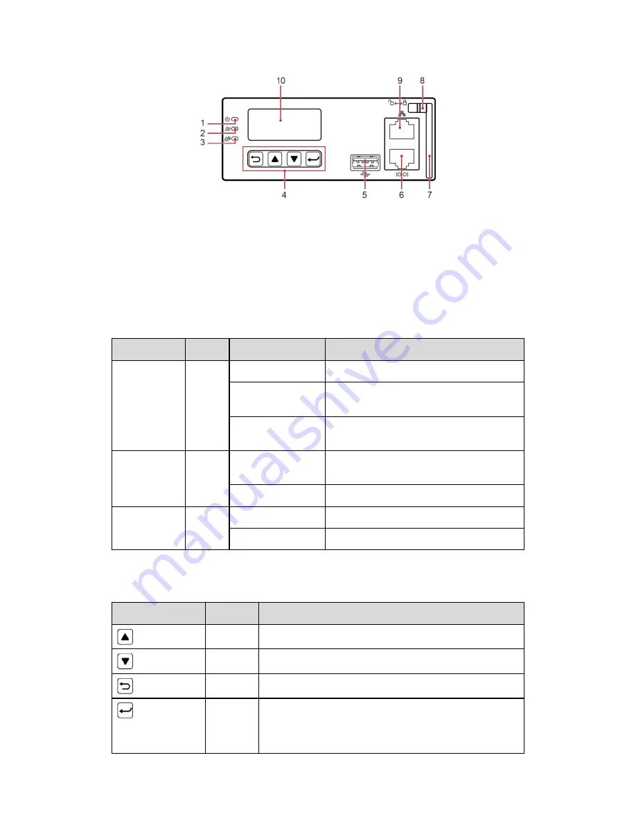
Figure 8 – DCSC panel 

(1) Run indicator 

(2) Minor alarm indicator 

(3) Major alarm indicator 

(4) Button 

(5) USB port (reserved) 

(6) RS485/RS232 port 

(7) Handle 

(8) Locking latch 

(9) FE port 

(10) LCD 


Indicators 

Name 

Color 

Status 

Description 

Run indicator  Green 

Off 

The DCSC is faulty or has no DC input. 

Blinking at 0.5 Hz 

The DCSC is running properly and 
communicating with the host properly. 

Blinking at 4 Hz 

The DCSC is running properly but is not 
communicating with the host properly. 

Minor alarm 
indicator 

Yellow  Off 

The DCSC does not generate any minor 
alarms. 

Steady on 

The DCSC generates a minor alarm. 

Major alarm 
indicator 

Red 

Off 

No critical or major alarm is generated. 

Steady on 

A critical or major alarm is generated. 

Table 4 – DCSC Indicators 

Buttons 

Button 

Name 

Description 


Up 

Scrolls up menus or sets parameter values. 


Down 

Scrolls down menus or sets parameter values. 


Back 

Returns to the previous menu without saving the settings. 


Enter 


Enters the main menu from the standby screen. 


Enters a submenu from the main menu. 


Saves the menu settings. 

Summary of Contents for DCPS

Page 1: ...8 1967 CPN 133202 Instruction Drawing Number P25 LDCPS 1 Tel 847 299 1188 Fax 847 299 3061 Revision A01 Rev Date 04 16 ECN 21144 La Marche Manufacturing Company www lamarchemfg com DCPS DC Power Syste...

Page 2: ...that neither liquids nor any wet material come in contact with any internal components Do not operate this unit outside the input and output ratings listed on the unit nameplate Do not use this unit f...

Page 3: ...installing the product Verify that you have all the necessary parts per your order for proper assembly CAUTION Failure to properly file a claim for shipping damages or provide a copy of the claim to L...

Page 4: ...2 2 1 Appearance 2 2 2 DCD 3 2 3 Rectifier 4 2 4 DCSC 5 2 5 DCU 8 3 Installation 11 3 1 Installation Preparations 11 3 1 1 Tools 11 3 1 2 Requirements for Cable Routing 11 3 1 3 Unpacking and Acceptan...

Page 5: ...Parameters before Using the SNMP Management 26 5 7 Connecting the Battery Supply 28 6 Maintenance 29 6 1 Performing Routine Maintenance 29 6 2 Troubleshooting Procedure 29 A Technical Specification 3...

Page 6: ...inputs 21 Figure 30 Installing power cables for two AC dual live wire inputs 22 Figure 31 Installing power cables for one AC dual live wire inputs 22 Figure 32 Login page 27 Figure 33 Setting SNMPv1...

Page 7: ...display and operations Web user interface Web UI for display and operations Display in multiple optional languages Hot swapping of rectifiers and the DCSC Rectifier power factor up to 0 99 1 4 Work Pr...

Page 8: ...r installing power distribution components including 1 U space for installing the DCSC Rectifier A maximum of four DCR s Controller DCSC User interface module DCU Table 1 Table Configurations 2 Compon...

Page 9: ...the DCPS Table 2 lists the power distribution specifications for the DCPS Figure 3 DC DCD for DCPS 1 RTN busbar 2 Wiring terminals for DC output power cables 3 Wiring terminals for battery cables Fig...

Page 10: ...age disconnection DC surge protection Differential mode 10 kA common mode 20 kA Battery circuit breaker Two circuit breakers A maximum of 200 A depending on customer requirements Table 2 Power Distrib...

Page 11: ...an alarm for power limiting due to ambient overtemperature The rectifier generates an alarm for shutdown due to ambient overtemperature or undertemperature The rectifier protects against AC input ove...

Page 12: ...erly but is not communicating with the host properly Minor alarm indicator Yellow Off The DCSC does not generate any minor alarms Steady on The DCSC generates a minor alarm Major alarm indicator Red O...

Page 13: ...ommunications Port Communications Parameter Communications Protocol FE port 10 100M auto adaptation HTTPS SNMP and RS485 RS232 port Baud rate 9600 bit s Master slave protocols All these ports are prot...

Page 14: ...es eight dry contact outputs six Boolean value inputs and seven sensor ports Figure 10 DCU panel Ports Port Type Silk Screen Description Sensor port TEM HUM Temperature and humidity sensor WATER Water...

Page 15: ...ions between the dry contacts and alarms see the appendix ALM1 Dry contact output 1 ALM2 Dry contact output 2 ALM3 Dry contact output 3 ALM4 Dry contact output 4 ALM5 Dry contact output 5 ALM6 Dry con...

Page 16: ...ilkscreen No Pin Definition 4 ENV_HUM WATER 1 12 V 2 WATER 3 GND 4 Not defined TEMP1 1 TEMP1 2 GND TEMP2 1 TEMP2 2 GND GATE 1 DIN7 2 JTD7 SMOKE 1 12 V 2 SMOKE BTEMP 1 BTEM1 2 GND Table 10 Pin definiti...

Page 17: ...of the same type should be bound together Cables of different types should keep a minimum distance of 30 mm from each other to avoid tangles Cables that are bound together should be close to each othe...

Page 18: ...ing the Subrack Rack Type U Shaped Slot Inward U Shaped Slot Outward 19 inch rack Normal installation three mounting holes Reverse installation three mounting holes 23 inch rack Normal installation th...

Page 19: ...tion 1 Mounting hole 1 reserved 2 Mounting hole 2 reserved default 3 Mounting hole 3 reserved Figure 15 Installing the subrack 3 2 2 Installing Subrack into a 23 Inch Rack For details about how to ins...

Page 20: ...re Step 1 Push the locking latch towards the left Step 2 Draw the handle downwards Step 3 Gently push a rectifier into its slot along the guide rail Step 4 Push the handle upwards Step 5 Push the lock...

Page 21: ...Step 3 Lift the top cover and take it out Figure 19 Removing the top cover CAUTION When you remove the top cover hold the top cover by hands to prevent it from falling into the subrack Step 4 Switch...

Page 22: ...subrack ground terminals Figure 21 Subrack ground terminals 1 Subrack ground terminals 3 5 Optional Installing Dry Contact Signal Cables Procedure Step 1 Press the contact plate using a flat head scre...

Page 23: ...SNMP device connect the communications cables to the FE port 3 7 Installing DC Output Power Cables Prerequisites DANGER Switch off all circuit breakers before installing power cables Procedure Step 1...

Page 24: ...to the battery wiring terminal Step 3 Connect the positive battery cable to the RTN busbar Figure 24 Installing battery cables 1 Battery string 2 2 Battery string 1 Step 4 Reinstall the top cover for...

Page 25: ...AC input protective cover as shown in Figure 26 Figure 26 Removing the AC protective cover Step 3 Route the AC input ground cable through an appropriate cable hole on the rear of the subrack Step 4 Se...

Page 26: ...Power Cables for Four AC Dual Live Wire Inputs Step 1 Route AC input power cables through an appropriate cable hole on the rear of the subrack Step 2 Secure the AC input power cables to the AC input...

Page 27: ...AC dual live wire inputs 1 Short circuit copper bar 1 2 Short circuit copper bar 2 Step 4 Reinstall the AC input protective cover Step 5 Reinstall the rear cover for the DCPS Optional Installing Powe...

Page 28: ...Input Step 1 Install short circuit copper bars Connect AC input terminals 1 L1 2 L1 3 L1 and 4 L1 by using short circuit copper bar 1 Connect AC input terminals 1 L2 2 L2 3 L2 and 4 L2 by using short...

Page 29: ...d output power cables and ground cables are correctly connected without being short circuited 4 3 Checking Cable Installation Check that all cables are securely connected Check that all cables are arr...

Page 30: ...ers Set battery string quantity battery rated capacity and battery installation time as required Main Menu Second Level Menu Third Level Menu Fourth Level Menu Default Value Setting Value Parameters S...

Page 31: ...f the rectifiers Main Menu Second Level Menu Third Level Menu Default Value Setting Value Parameters Settings Energy Saving Hibernation enable Disable Enable Table 14 Setting the hibernation parameter...

Page 32: ...d Level Menu Third Level Menu Default Value Setting Value Setting Wizard Network Parameters IP Address 192 168 0 10 Set this parameter based on the address assigned by the network administrator Subnet...

Page 33: ...ess in the address box on the laptop Log in to the Web UI on the login page shown in Figure 32 The preset user name is admin and the preset password is 000001 Figure 32 Login page Step 6 On the System...

Page 34: ...fter you correctly set the battery parameters Procedure Step 1 Switch off the upper level circuit breaker Step 2 Switch on the battery circuit breaker Step 3 Switch on the upper level circuit breaker...

Page 35: ...unit a general inspection Check the following 1 Check DC output cables connections battery type and number of cells against the unit s rating 2 Check unit specifications against customer order 3 Chec...

Page 36: ...oad THD I 10 DC output Output voltage range 42 V DC to 58 V DC Default output voltage 53 5 V DC Output power Maximum output power Output power of a single rectifier x Number of rectifiers Regulated vo...

Page 37: ...pecifications Conducted emission CE Input port CISPR 22 EN 55022 class B Output port CISPR 22 EN 55022 class A Radiated interference CISPR 22 EN 55022 class B Harmonic current IEC 61000 3 12 Voltage f...

Page 38: ...ture Power system 4 U x 19 inch x 17 7 inch H x W x D Weight 50 71 lb 23 kg without rectifiers and DCSCs Protection level IP20 Installation mode Installed in a 19 inch or 23 inch rack Cable routing Ro...

Page 39: ...ng closed alarm open normal can be changed ALM3 Reports alarms for rectifier faults The default setting closed alarm open normal can be changed ALM4 Reports alarms for DC surge protective device SPD f...

Page 40: ...cure IEC International Electro technical Commission IP Internet Protocol LCD Liquid Crystal Display LLVD Load Low Voltage Disconnection LSI Large Scale Integrated MTBF Mean Time Between Failures PCB P...

Page 41: ...er installation installation adjustments and service arrangements Should minor adjustments be required the local La Marche sales representative should be contacted to provide this service only All sal...

Page 42: ...36 Document Control and Revision History Part Number 133202 Instruction Number P25 LADCPS 1 Issue ECN 21023 12 15 21023 12 15 21144 04 16...

Reviews: