background image


                                        Chapter Ei ght Web Management Software                                                                 


-39- 


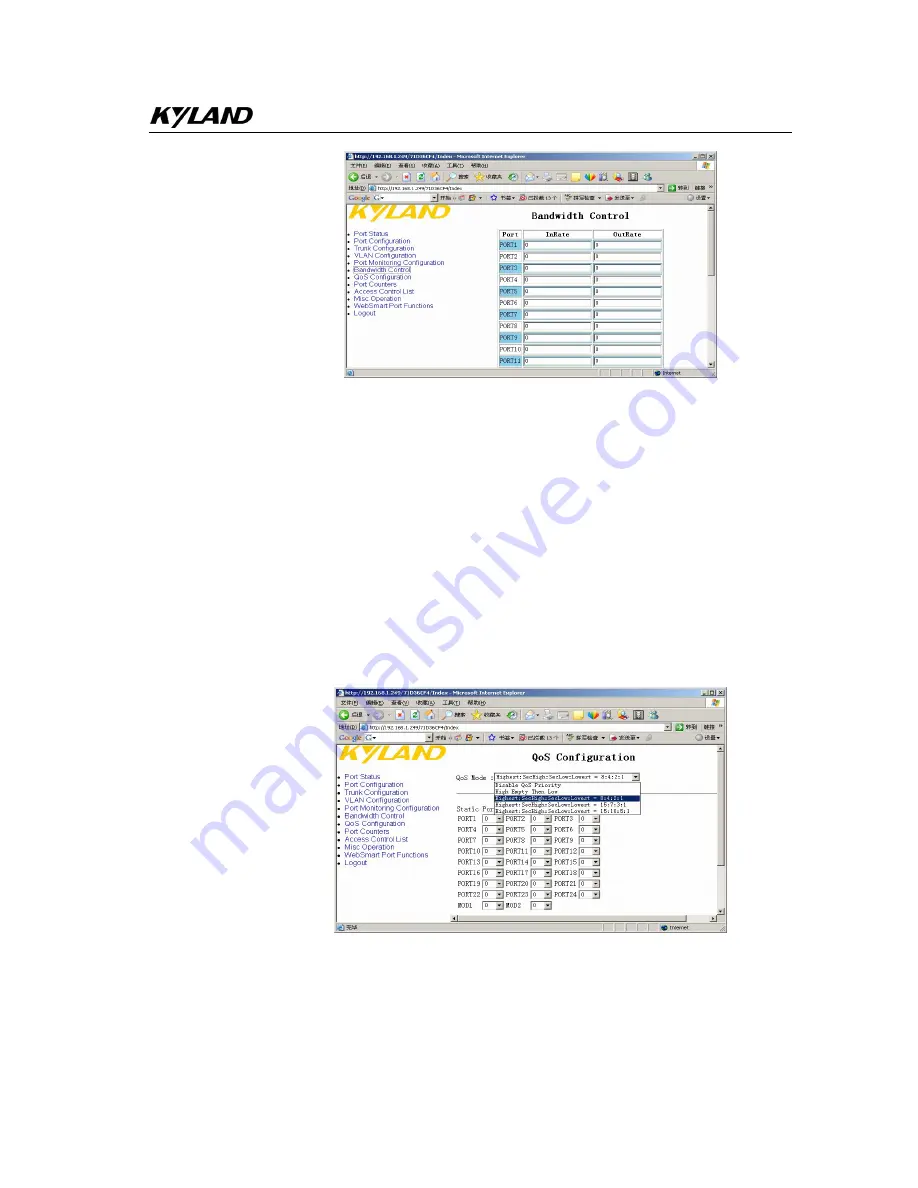
Figure 8-12 Port Rate Configuration 

8.9


QOS 

Click the left menu:

QOS Configuration

  to enter into QOS page: 

Select  QOS  mode

Disable  /  High  Empty  Then  Low  /  weight8:4:2:1  /  15:7:3:1  / 

15:10:5:1 

QOS default mode 

Weight 8:4:2:1 

Options for each port

0~7 

802.1p priority mode

Highest / SecHigh / SecLow / Lowest 

Click APPLY to finish: 


  Figure 8-13 QOS 

Summary of Contents for KIEN3016M

Page 1: ...KIEN3016M 3024M Industrial Ethernet Switch User s Manual KYLAND Telecom Technology Co Ltd...

Page 2: ...annotated or duplicated in any form or by any means without the prior written permission of KYLAND Corporation Publisher KYLAND Telecom Technology CO LTD Address 5 F Office Building Transport Center...

Page 3: ...ide users with references in startup expansion and routine maintenance It is a practical teaching material that can be used by users in trainings and helps the relevant technical personnel to increase...

Page 4: ...quipments should be firmly interconnected and frequently checked In the following cases please immediately disconnect the power supply and contact with our company 1 Water gets into the equipments 2 E...

Page 5: ...ring operation The implications of these signs are as follows Warning pay special attention to the notes behind the mark improper operation will result in serious damage of the switch or injury of ope...

Page 6: ......

Page 7: ...e 9 3 1 System Structure 9 3 2 Switch Structure 10 3 2 1 Chassis 10 3 2 2 Front Panel 10 3 2 3 Rear Panel 11 Chapter Four KIEN3024M Hardware Structure 15 4 1 System Structure 15 4 2 Switch Structure 1...

Page 8: ...ion 35 8 6 VLAN Configuration 35 8 6 1 Port based VLAN Configuration 36 8 6 2 802 1Q based VLAN Configuration 36 8 7 Port Monitoring Configuration 37 8 8 Port Rate Configuration 38 8 9 QOS 39 8 10 ACL...

Page 9: ...on 47 9 2 4 Trunk Configuration 48 9 2 5 VLAN Configuration 48 9 2 6 Port Monitoring Configuration 51 9 2 7 Bandwidth Control 52 9 2 8 QoS Configuration 53 9 2 9 Port Counters 53 9 2 10 Access Control...

Page 10: ......

Page 11: ...se TX and half duplex or full duplex and can be connected automatically in MDI MDI X way In the front panel there are four slots for fiber ports and can offer 0 to 4 pairs of fiber ports 100Base FX of...

Page 12: ...s Powerful management realizes VLAN IGMP Snooping TRUNK port mirroring etc Hyper terminal interface offers convenience for project field Optional Industrial Power Design Industrial AC power supply 220...

Page 13: ...the case do not overly extend the hard object into the case to avoid damage of the equipments inside the case After opening the case check the amount of equipments including main unit of parts of equi...

Page 14: ......

Page 15: ...net Port Physical interface RJ 45 shielded RJ 45 10 100Base T TX auto negotiatable Standard IEEE802 3 Transmission Distance 100m Fiber Port Optical Power 13dbm SM 20dbm MM Optical Sensitivity 28dbm SM...

Page 16: ...ort Physical interface RJ 45 shielded RJ 45 10 100Base T TX auto negotiatable Standard IEEE802 3 Transmission Distance 100m Fiber Port Optical Power 13dbm SM 20dbm MM Optical Sensitivity 28dbm SM 35db...

Page 17: ...en for link status ON for active connection BLINK for active network OFF for no connection 2 3 Service Functions offer such service functions as following 1 LED Indicator The LEDs of the front panel i...

Page 18: ...service functions You can configure the service functions on the Eth trunk port but note to configure the OoS in the physical ports 5 Multicasting IGMP IGMP means Internet Group Multicast Protocol KIE...

Page 19: ...er Power Port EMC protections Figure 3 1 Hardware Structure System hardware mainly consist the following parts 1 Switching network controller employs ASIC chip technology offering layer 2 wire speed t...

Page 20: ...sis of KIEN3016M 3 2 2 Front Panel The front panel of KIEN3016M is shown in Figure 3 3 KIEN3016Industrial Ethernet Switch D C A B RUN DPX LINK 1 2 5 3 4 6 8 7 13 12 9 1011 141516 LINK ACT 10M 100M Fig...

Page 21: ...0 to 4 fiber ports of 100Base FX The connector is SC The fiber ports must be used in pair xT is for transmitting and is connected to remote xR port xR is for receiving and is connected to XT port X me...

Page 22: ...INDOWS system to configure and manage the switch CONSOLE port Baud rate 9600 data 8 check no stop 1 traffic control no You should connect the RS232 console port with the 9 pin serial port of PC as in...

Page 23: ...supply If the product shows AC power supply AC220V use this terminal to connect power supply This terminal offers a fuse socket and you can change t he fuse easily 2A fuse is used here 1 Plug a 2A fus...

Page 24: ...KIEN3016M 3024M Industrial Ethernet Switch User s Manual 14 Figure 3 7 b 2nd step...

Page 25: ...controller employs ASIC chip technology offering layer 2 wire speed transfer of data packets 6 Integrated module of transmitting and receiving 7 Industrial isolated power supply with protection of ov...

Page 26: ...2021222324 F Figure 4 3 Front Panel Indicators show the status of system operation and ports to find and correct faults The Table 4 1 shows the meanings of these LED indicators in the front panel Tab...

Page 27: ...M offers 24 RJ45 ports of 10Base T 100Base TX Each port is adaptive and supports for auto MDI MDI X connection You can connect it to terminal device server hub or switches by straight through or cross...

Page 28: ...Ethernet cable connection DC Power Supply If the product shows DC power supply DC24V DC 48V use this terml to connect power supply The power cable must more than 0 3 2 shown in Figure 4 6 24V Ter m i...

Page 29: ...et and you can change t he fuse easily 2A fuse is used here 1 Plug a 2A fuse into the socket and press a standby sue into the slot for next time change as in Figure 4 7a 2 As in Figure 4 7b plug the f...

Page 30: ......

Page 31: ...e uplink fiber TP port is available and ready 5 Avoid direct sunshine and keep it away from heating sources or areas where have strong electromagnetic interference 6 Prepare for necessary tools for ra...

Page 32: ...tion After properly mounting KIEN3016M KIEN3024 it is ready for cable mounting and connection mainly including cable connection for the following interfaces 1 Service interface KIEN3016M KIEN3024 prov...

Page 33: ...n it is not in use cover SC port with the rubber sleeve to protect the optical fiber terminator 2 Check whether the optical fiber terminator is clean Slightly wet a clean tissue or cotton ball and car...

Page 34: ...If cables power line and grounding conductor are laid in the same channel cables power line and grounding conductor should be not folded or blended together If a cable line is overly long coil and pl...

Page 35: ...kage is lost At the same time the yellow lamp on the corresponding port should keep on computer network interface card operates in 100M state or keep off computer network card operates in 10M state an...

Page 36: ...6 AT AR BT BR CR CT DT CONSOLE DR ON OFF AC220V DC POWER POWER 1 2 KI EN3016M KI EN3024M Figure 6 2 Testing Fiber Ports PING Command The IP address of the testing computer 1 is 192 168 100 10 and the...

Page 37: ...uilding For the applications in power transportation energy water and factory automation KIEN3016M make use of the 0 to 4 pair of fiber ports to form multiple network topology flexibly and offers 16 p...

Page 38: ...suitable for the connection layer and building convergence layer You can use the cat5 cable to connect the 10 100M broadband and one pair fiber port of 100Base FX to uplink to the convergence point t...

Page 39: ...automation KIEN3024M make use of the 0 to 2 pair of fiber ports to form multiple network topology flexibly and offers 24 ports of 10Base T 100Base TX to connect multiple terminal devices to form chai...

Page 40: ...EN 3024 KI EN 3024 KI EN 3024 Aggregat i on Sw i t ch Figure 7 6 KIEN3024M Broadband Network 7 3 System Configurations KIEN3016M and KIEN3024M are integrated structures offering 16 or 24 Ethernet por...

Page 41: ...IEN3016M 16 x 10Base T 100Base TX RJ 45 KIEN3016M 4M 4 x 100Base FX MM 16 x 10Base T 100Base TX RJ 45 KIEN3016M 3M 3 x 100Base FX MM 16 x 10Base T 100Base TX RJ 45 KIEN3016M 2M 2 x 100Base FX MM 16 x...

Page 42: ......

Page 43: ...ment will be introduced in next chapter Open IE browser and enter IP address press ENTER to login with user name of admin password of admin click advanced setting Figure 8 1 Login Page 8 2 Main Page T...

Page 44: ...tus to show the status of each port enable up down 100F 10T traffic control ON OFF Figure 8 3 Port Status Page 8 4 Port Configuration Click Port configuration to enter into the page port configuration...

Page 45: ...er into the page of trunk For KIEN3016M up to 7 TRUNK is possible You can bind 2 to 8 ports for each trunk MOD1 and MOD2 must be binding together without other ports Figure 8 5 Port Trunking 8 6 VLAN...

Page 46: ...the port For example port 1 4 is member state and click APPLY key VLAN is configured successfully Back to VLAN CONFIGURATION and check the VLAN state Click VLAN 4 to check the configurations Figure 8...

Page 47: ...ng to enter into Advanced 802 1Q VLAN Setting interface set the port as nonmeber drop forward untag drop forward Figure 8 9 802 1qQ based VLAN Configuration b 8 7 Port Monitoring Configuration Click P...

Page 48: ...guration Select mirrored and mirroring port and click APPLY to finish configurations Figure 8 11 Select Port 8 8 Port Rate Configuration Click Bandwidth Control to enter into Bandwidth Control page an...

Page 49: ...Click the left menu QOS Configuration to enter into QOS page Select QOS mode Disable High Empty Then Low weight8 4 2 1 15 7 3 1 15 10 5 1 QOS default mode Weight 8 4 2 1 Options for each port 0 7 802...

Page 50: ...APPLY to finish Figure 8 14 ACL 8 10 1 Ipv4 ACL Configuration Item option default Group ID 1 255 max 255 ACL group 0 Action Permit Deny a Permit Permit packet cross switch b Deny Drop packet Permit An...

Page 51: ...o 0 255 If protocol not find in L4 Protocol field you can directassign number 0 TCP Any FTP 21 HTTP 80 Any Port 0 65535 If TCP port not find in TCP field you can direct assign number 0 UDP Any TFTP 69...

Page 52: ...onfiguration to configure Broadcast storm and set the bandwidth of the broadcasting data as 1 2 1 4 1 8 1 16 OFF Collision retry forever is Enable or disable Configure the MAC address aging time 150ms...

Page 53: ...n to enter IGMP Snooping starting page and select Disable enable Click APPLY to finish Figure 8 17 IGMP Configuration 8 11 4 IPAddress Configuration Click IP Configuration to enter page and change the...

Page 54: ...3024M Industrial Ethernet Switch User s Manual 44 8 11 5 Update Configuration Click Firmware Update to enter into update page and key into IP address and software name click APPLY to finish Figure 8...

Page 55: ...to next configuration enter Select action esc Back to previous status 9 1 2 Console Command Table 9 2 Key Description Quit Exit this page and return to previous menu Edit Configure all items Press Ent...

Page 56: ...selected list 9 2 Serial Port Console Interface 9 2 1 Serial Port Console Main Page Enter into hyper terminal and configure the parameters of port connect PC with KIEN3016M or KIEN3024M click ENTER to...

Page 57: ...Status 9 2 3 Port Configuration In figure 9 2 select Port Configuration to enter into page as in figure 9 4 select Edit to configure port for Enable Disable Auto Spd Dpx Flow Ctrl Auto on off Spd Dpx...

Page 58: ...or TRUNK1 move and select port when the state of port is changed from to V the port is trunked into TRUNK1 Click ESC quit Click Save and ENTER to save configurations Figure 9 5 Port Trunking 9 2 5 VLA...

Page 59: ...ration Select Edit and click enter VLAN Mode Portbased Select ADD click enter to add VLAN enter ADD Portbased VLAN Group as shown in Figure 9 8 select Group ID ID 1 4094 Select port port1 port24 mod1...

Page 60: ...d click enter VLAN Mode 802 1q Select ADD and click enter to add VLAN enter ADD A 802 1Q VLAN Group As shown in Figure 9 10 select Group ID ID 2 4094 select port port1 port24 mod1 mod2 any Save the co...

Page 61: ...at forward to forward the untagged packets drop means drop Save the configuration after finish configuration 9 2 6 Port Monitoring Configuration In figure 9 2 select Port Monitoring Configuration clic...

Page 62: ...7 Bandwidth Control In figure 9 2 select Bandwidth Cotrol and click enter to enter into Bandwidth Cotrol page as shown in figure 9 14 select the inrate and outrate and save Port1 24 rate can be set u...

Page 63: ...1 default at weight 8 4 2 1 The data are queued in two ways 802 1p based and port based For 802 1p based there are such levels Highest SecHigh SecLow Lowest For port based there are such levels 7 0 O...

Page 64: ...ation click enter to enter Acess ACL Configuration page as shown in figure 9 17 Figure 9 17 Acess ACL Configuration 9 2 10 1 Ipv4 ACL Configuration As shown in Figure 9 17 select Ipv4 ACL Configuratio...

Page 65: ...Vlan id b Specify A certain vlan id VID 1 4094 0 IP Fragment Uncheck Check Uncheck a Uncheck Not check IP fragment field b Check Check IP fragment field Src IP Any Specify Any a Any Any IP address b S...

Page 66: ...TCP 6 UDP 17 Any Proto 0 255 0 If protocol not find in L4 Protocol field you can direct assign number TCP Any FTP 21 HTTP 80 Any Port 0 65535 0 If TCP port not find in TCP field you can direct assign...

Page 67: ...Figure 9 22 Select the parameter in table 8 4 Table 8 4 In figure 9 21 select list and click enter to show the list of Non IP v4 Group as shown in figure 9 22 Items Option Default value Group ID 1 25...

Page 68: ...ect Misc Operation click enter to enter Misc Operation page as shown in figure 9 23 Figure 9 23 9 2 11 1 Advanced Switch Configuration In figure 9 23 select Advanced Switch Configuration click enter t...

Page 69: ...0 20 minutes 5 minutes Time Web Auto Logout Time Never 5 10 20 minutes 5 minutes Figure 9 24 9 2 11 2 Password Setting In figure 9 23A select PASSWORD SETING click enter to enter PASSWORD SETING page...

Page 70: ...g IGMP In figure 9 23 select Multicast Filtering IGMP click enter to enter Multicast Filtering IGMP page as shown in Figure 9 26 to enable IGMP according to Table 9 7 Table 9 7 Items Option Default Va...

Page 71: ...as shown in Figure 9 27 to configure according to table 9 8 Table 9 8 Items Option Default Value IP Address 192 168 1 1 is represent a digit from 0 9 is range from 0 to 255 Subnet Mask 255 255 255 0...

Page 72: ......

Page 73: ...he RJ 45 connectors Fig A 1 illustrates how to number the RJ 45 connector please confirm the consistence of the direction when it is inserted 1 8 8 1 Fig A 1 RJ 45 Connector Pin distribution of 10Base...

Page 74: ...n the 10Base T 100Base TX pin assignment refer to table A 1 Table A 1 10Base T 100Base TX Pin Assignment Pin MDI X signal name MDI signal name 1 Receiving data RD Output data TD 2 Receiving data RD Ou...

Page 75: ...65...

Page 76: ......

Page 77: ...Cable type and specifications Cable Type Max length Connector 10Base T Cat 3 4 and 5 100 ohm UTP 100m 328 foot RJ 45 100Base TX Cat 5 100 ohm UTP 100m 328 foot RJ 45 100Base FX 50 125 or 62 5 125 m co...

Page 78: ...tion function Traffic Control It is a congestion control mechanism The network equipment sends the data to the equipment which has overloaded and causes the port to congest The traffic control can pre...

Page 79: ......

Page 80: ......

Reviews: