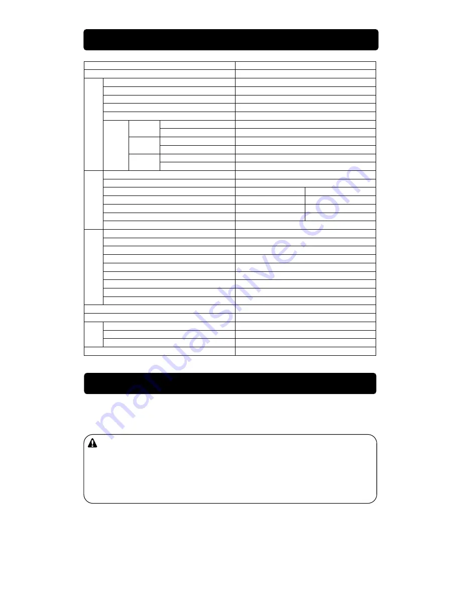
kWiet Power dgw400dm Owner'S And Operator'S Manual Download Page 8

- 5 - 


Model 

DGW400DM 

Generating Method 

Rotating Field 

Rated Current                                              (A) 

370 / 390 

Rated Voltage                                              (V) 

34.8 / 35.6 

Duty Cycle                                                  (%) 

60 

Rated Speed                                          (min

-1

3000 / 3600 

No Load Voltage                                          (V) 

MAX 85 

Current Adj. Range (A) 

90 – 380 / 110 - 400 

Single 

Welding Rod            (

Ф

2.6 - 8.0 

Current Adj. Range (A) 

50 – 190 / 55 - 210 

Dual 

Welding Rod            (

Ф

2.0 - 4.0 

Current Adj. Range (A) 

40 - 240 

W

e

ld

in

g

 G

e

n

e

ra

to

O

u

tp

u

C

h

a

n

g

e


Eco 

Welding Rod            (

Ф

2.0 - 5.0 

Rated Frequency                                      (Hz) 

50 / 60 

Rated Speed                                        (min

-1 

3000 / 3600 

Phase 

1-Phase 

3-Phase 

Rated Voltage                                              (V) 

220-240 

380-415 

Power Factor 

1.0 

0.8 

Rated Output                                          (kVA) 

15 

A

C

 G

e

n

e

ra

to

Rating 

Continuous 

Model 

Kubota D1005 

Type 

Vertical, Water-Cooled 4-Cycle Diesel Engine 

Displacement                                                (L) 

1.001 

Rated Output                                  (kW/min

-1

16.5 / 3000    or    19.1 / 3600 

Fuel 

ASTM No.2-D Diesel Fuel or Equivalent 

Lubricant Oil 

API Class CC or better 

Lubrication Oil Volume                                (L) 

5.1 (Effective 1.4) 

Cooling Water Volume                                (L) 

4.3 (Sub Tank Capacity 0.6 L included) 

E

n

g

in

e


Starting Method 

Starter Motor 

Battery 

55B24L (Japanese Industrial Standard) 

Fuel Tank Capacity                                                  (L) 

37 

Length                                                      (mm) 

1519 

Width                                                        (mm) 

700 

D

im

e

n

s

io

n


Height                                                        (mm) 

760 

Dry Weight                                                              (kg) 

469 


 Arc Welding 

 Electric Tools and Home Appliances 

 Power Source for lights 


Caution: Damage to the equipment or other properties 

 The equipment is designed for the above purposes only. Do not use it for the 

other purpose. When it will be used for the equipment with the microcomputers 
control or for the ultra-precision devices, the load may be malfunctioned.


 Whenever connecting to use medical equipment or appliances, be sure to consult 

with the medical equipment company, doctor or hospital personnel.


2. Specifications 

3. Use 

Summary of Contents for dgw400dm

Page 1: ...al Water Cooled 4 Cycle Diesel Engine DGW400DM 380A K X750 023 89 0 X750803 710 0 CAUTION Do not operate the Generator Welder or any other appliance before you have read and understood the instructions for use and keep near for ready use ...

Page 2: ......

Page 3: ...ccessed at all times to order parts or arrange for repair Contact the retail outlet where this equipment was purchased if any parts are lost the equipment becomes soiled or is otherwise damaged in any manner Consult with the retail outlet where the equipment was purchased if any of the points are unclear or you would like further information Be sure to note the model name and serial number of your...

Page 4: ...ecking Coolant Water 15 6 3 Checking Fuel 16 6 4 Checking Fuel Engine Oil and water Leakage 17 6 5 Checking Battery 17 7 Operation 18 7 1 Starting 18 7 2 Stopping 19 7 3 Emergency Stopping 19 8 Welding Operation 20 8 1 Selection Welding Cable 20 8 2 Polarity 21 8 3 Connection Welding Cable 21 8 4 Duty Cycle 22 8 5 Welding 22 9 Generator Operation 23 9 1 Output Range 23 9 2 Output Limitation 24 9 3...

Page 5: ...always wait until the engine cools down before refueling Always wipe any drip of Diesel fuel or lubrication oil Do not use this equipment when a leak is found Repair the equipment before use Temperature around muffler and exhaust can get extremely high Keep any inflammable items such as fuel gas paint etc away from the equipment Keep any inflammable items and easily burning items away from the pla...

Page 6: ...lug during operation hot oil may cause some injury Be sure to wear leather gloves apron shoe covers eye protection glass es mask safety shoes safety cap and long sleeve shirts because welding splashes spatters Do not open the radiator cap while operating this equipment or immediately after stopping the equipment to avoid sustaining burns from hot vapor Caution Injuries When lifting the equipment a...

Page 7: ...ed locations Order the necessary labels by numbers in parentheses 1 Suffocation from Exhaust Fume No X505 007590 2 Suffocation from Welding Fume No X505 007600 3 Fire No X505 007650 4 Electric Shock No X505 007610 5 Injury No X505 007630 6 Burn No X505 007620 7 Burn No X505 007640 8 Electric Shock No X505 004970 INSIDE 1 2 3 4 4 5 6 7 8 ...

Page 8: ... 19 1 3600 Fuel ASTM No 2 D Diesel Fuel or Equivalent Lubricant Oil API Class CC or better Lubrication Oil Volume L 5 1 Effective 1 4 Cooling Water Volume L 4 3 Sub Tank Capacity 0 6 L included Engine Starting Method Starter Motor Battery 55B24L Japanese Industrial Standard Fuel Tank Capacity L 37 Length mm 1519 Width mm 700 Dimen sion Height mm 760 Dry Weight kg 469 Arc Welding Electric Tools and...

Page 9: ...R SWITCH RECEPTACLE BONNET GROUNDING TERMINAL FREQ METER EMERGENCY STOP SWITCH AMP METER 3 P VOLT METER VOLTAGE ADJ DIAL CURRENT ADJ DIAL B CURRENT ADJ DIAL A WELDING TERMINAL A WELDING TERMINAL B HOUR METER FUEL METER 3 P RECEPTACLE 3 P BREAKER 1 P BREAKER 1 P RECEPTACLE EARTH GROUNDING TERMINAL ...

Page 10: ... 7 Engine Key 1 Set Tool Kit Door Key 2 Set Accessories Owner s and Operator s Manual HANDLE MUFFLER EXHAUST PORT TOP PLATE HANDLE FUEL INLET LIFTING LUG Grounding Rod ...

Page 11: ... and you will not do anything when Eco is used for AC power supply 5 2 Remote Control Option Using the remote control box the remote control to adjust the welding current makes it possible Remote Control Box Connection 1 Remove Eco plate M4 Screw 2 pieces 2 Insert the plug of the extension cable reel into A side or B side receptacle 3 Insert the plug of the remote control box into the receptacle o...

Page 12: ...p while operating this equipment or immediately after stopping the equipment to avoid sustaining burns from hot vapor Do not touch the engine and muffler during operation and immediately after stopping the equipment for the temperature can reach extremely high When the water temperature rises abnormally the coolant water temperature monitor lamp will flash and the automatic shutoff will be engaged...

Page 13: ... pressure monitor cannot detect the degradation of engine oil itself Please check the engine oil periodically and change if needed Refer to No 11 Maintenance Check the fuse next when the abnormality other than WATER TEMP BATTERY CHARGED OR OIL PRESSURE is detected If the fuse is burned out consult with our authorized distributor or our engineering section because there may be an abnormality of ele...

Page 14: ...ne and muffler during operation and immediately after stopping the equipment for the temperature can reach extremely high When the engine oil pressure drops during operation the oil pressure monitor lamp will flash and the automatic shutoff will be engaged 1 Stop the engine 2 Open the side door 3 Turn the selector switch and the metal bus bars to the other frequency as per the drawing 4 Start the ...

Page 15: ...risen due to the troubles as insulation failure of the load while the generator is running And cutting off the circuit for protection against any accident such as electrical shock resulting from the trouble Note The 3 phase circuit breaker trips to protect the loads whenever AC power is used where the selector switch is in the Eco position The specifications of the earth leakage relay Rated Sensit...

Page 16: ... Earth Leakage Relay has activated Caution Electric Shock Injuries Be sure to disconnect all the loads to the equipment when turning the breakers ON again after the earth leakage relay has activated When the earth leakage relay has activated the earth leakage indication lamp turns ON and also the 3 P circuit breaker lever trips to the middle of ON and OFF In the case stop the engine promptly and f...

Page 17: ...ne automatically moves to high speed whenever welding operation or electric supply starts Caution Damage to the equipment or other properties Turn always the slow down switch to OFF when the load is incorporated with any magnet switch Note When the load of less than 0 5A is connected to use the Slow Down feature does not function sometimes Therefore turn the switch to OFF When welding operation or...

Page 18: ...ngine oil Note Use the API class CC or better Viscosity and Temperature Temperature 20 C or more 10 C 20 C 10 C 40 C Oil Viscosity SAE30 SAE20 SAE 10W 30 6 2 Checking Coolant Water Warning Injuries Close all doors and place locks during operating this equipment to avoid injuries by unintentionally touching cooling fan and fan belt Caution Burns Do not open the radiator cap while operating this equ...

Page 19: ... any leak is found Repair the equipment before use Check for the fuel level in the tank Add if necessary Note Use Diesel fuel ASTM D975 No 2 D in the event ambient temperature reaches down to 5 C The engine is designed to use either No 1 D or No 2 D Diesel fuel However for better economy use No 2 D Diesel Fuel whenever possible At temperatures less than 7 C 20 F No 2 D fuel may pose operating prob...

Page 20: ...ly with eyes flush with a lot of water and contact your physician immediately Caution Explosion Do not use the equipment or charge the battery in the case the battery fluid level is lower than the LOWER level Battery may emit some combustible gas so keep it away from fire and sparks Caution Explosion Battery may emit some combustible gas so keep it away from fire and sparks 1 Check the fluid level...

Page 21: ...ay from the equipment Always operate this equipment on flat surface and at least 1 meter away from any objects wall box etc Caution Suffocation from Exhaust Fume Do not point the exhaust fume toward pedestrians or building Caution Injuries Always place the equipment on a flat and stable surface to keep the equipment from sliding Be sure to lock the wheels for the wheeled models Before starting the...

Page 22: ...gine speed becomes stable when the air is extracted Note Never turn the engine NORMAL speed or connect the loads until the air is extracted completely the engine speed becomes stable 7 2 Stopping 1 Turn Push down the breakers 1 P and 3 P to OFF 2 Turn the Slow Down switch to ON 3 Keep the engine idle cooling down for about 5 minutes 4 Turn the starter switch to STOP 5 After the engine has stopped ...

Page 23: ...ncy stop feature The engine does not start again though the starter motor is running without releasing the emergency stop feature 8 1 Selection Welding Cable Select the cable with proper gauge based on the allowable amperage and the length per the table shown below The welding capacity is to reduce if the small gauge cable is used Note Welding cables should be used unstrained When the welding cabl...

Page 24: ...ingle Single Dual Welding rod φ2 0 φ5 0 Welding Rod φ2 6 φ8 0 Welding Rod φ2 0 φ4 0 Welding Output Terminal A Welding Output Terminal A Welding Output Terminal A and Welding Output Terminal B Note Be sure to crimp a crimping terminal to a cable and connect the cable to welding output terminal Otherwise welding output terminals may burn out by the heat caused by insufficient connections Do not use ...

Page 25: ...ing Fire Keep any inflammable items and easily burning items away from the place in welding because welding splashes spatters Caution Injury to Eyes and Skin Be sure to wear spark protection glass es Refer to the table below long sleeve shirts gloves etc in order to protect eyes and skin from harmful spark in welding Standards for Arc Proof Glasses Japanese Industrial Standard Filter No 7 8 9 10 1...

Page 26: ...tion Freq MIN 1 2 3 4 5 MAX Eco 40 60 100 140 180 220 240 50Hz 90 120 190 250 320 360 380 1 Person Single Use 60Hz 110 140 200 260 320 380 400 50Hz 50 70 100 130 160 180 190 2 Persons Dual Use 60Hz 55 70 110 140 170 200 210 The values shown in the table are for reference only The length and the ambient temperature affect the value When the remote control box is used the values change to some degre...

Page 27: ...otor 1 5 Mercury Bulb High Power Factor Type 1 2 Submersible Pump Compressor etc Induction Motor 1 2 6 0 Series Motor Motor with brush Induction Motor Brushless Motor The value described is OUTPUT for Induction Motor loads and POWER CONSUMPTION for the other equipment Note Be sure to use the frequency designated in the equipment incorporated in mercury bulb or induction motor The load incorporated...

Page 28: ...ou should repair the leaking place first of all Caution Injuries Be sure to insert a plug to a receptacle after confirming that all the switches in the loads are positioned to OFF Be sure to select the correct frequency designated in the loads Refer to No 5 4 Frequency Change Caution Damage to the property Aftermath Whenever connecting to use medical equipment or appliances be sure to consult with...

Page 29: ...ctor switch is positioned to Eco and AC power is used the 3 P circuit breaker trips off to shut down the circuit Stop using AC power and follow the above procedure to restore the circuit breaker The circuit breakers 3 P and 1 P react on the AC power supply circuit only In the simultaneous use of welding and generating there sometimes happens overload to the engine Refer to the following table and ...

Page 30: ...e startup checks Request for the maintenance item with mark to the authorized distributor or our engineering section Always use our genuine parts of replacement To optimize the use of this generator welder we recommend the periodical equipment checks and maintenance based on the following matrix Use the hour meter as a guide for the operating time Checking Time Checking Items Startup Check 50th ho...

Page 31: ...gine Valve Clearance Adjust ment Lapping 20 Check Adjust Injection Nozzle 21 Check Adjust Injection Pump 1 Oil Change 1 Remove the oil plug 2 Loosen the oil drain plug and allow the oil to drain fully 3 Reinstall the oil drain plug 4 Checking the oil level by the oil level gauge add oil into the oil filler to fill up to the max level about 5 0 liter 5 Reinstall the oil plug hand tight Note Refer t...

Page 32: ...orized distributor or our engineering section Oil Filter Part No 16271 32092 Kubota 3 Clean Change Air Filter Element Cleaning 1st time 50th hour 2nd time and after Every 100 hours Replacement Every 400 hours 1 Loosen the wing bolts in the air cleaner and remove the air element 2 Clean or replace the air element The element is adhered with dried contaminants Blow up compressed air from inside the ...

Page 33: ... Element Part No 15521 43161 Kubota 5 Drain Water from Fuel Tank Draining Water Every 200 hours 1 Unscrew the fuel drain plug 2 Reinstall the drain plug after draining water completely Note Change the packing whenever changing oil Packing Part No 6C090 58961 Kubota 6 Changing Coolant Water Draining Water Every 200 hours Total Coolant Water Capacity 4 3 liter including sub tank cap 0 6 liter 1 Open...

Page 34: ... tank and the fuel strainer 4 Clean all parts cover the generator welder and keep it in the storage away from dust and humidity Note Recharge the removed battery once a month Warning Electric Shock Do not operate the equipment if the equipment or you are wet Before performing any equipment check or maintenance stop the engine Caution Injuries When performing equipment check and maintenance always ...

Page 35: ...ng to Selection Welding Cable 6 Connect securely 7 Stop using AC Power 8 Remove the cause of the short circuit 9 Wait until the equipment cools down the lamp to OFF Excessive Welding Arc 1 Output selector switch is to SINGLE 2 Wrong current adjustment dial position 1 Turn to ECO or DUAL 2 Turn the dial counterclockwise No AC Output 1 The breaker 3 P or 1 P positions to OFF 2 Output selector switch...

Page 36: ... 33 14 Engine Wiring Diagram ...

Page 37: ... 34 15 Generator Wiring Diagram ...

Page 38: ......

Page 39: ......

Page 40: ... 2013 ...

Reviews: