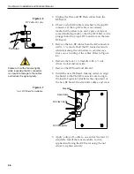
10. Reattach the RF cables, making certain that the RF
cable originally attached to the top RF connector
on the old RF Board is connected to the top RF
connector on the new RF Board.
11. Attach the Data and RF Flash cables to the
RF Board.
12. Insert the split rubber grommet surrounding the
Data and RF Flash cables into the small slot on the
new RF Board cover.
13. Secure the RF Board cover using the nuts and
washers removed in Step 1.
4.5
Antenna Gyro Assembly
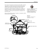
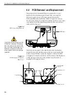
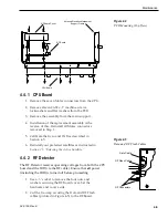
1. Remove the printed circuit board (PCB) cover,
illustrated in Figure 4-2, using a #2 Phillips
screwdriver and a
3
⁄
8
" nut driver/socket.
2. Use the
3
⁄
8
" nut driver/socket to remove the four
nuts and washers securing the Antenna Gyro to
the Antenna Reflector. The nut on the bottom right
also secures another P-clip to the Antenna
Reflector. Set the nuts and washers aside.
3. Disconnect the 7-pin Molex connector from the
PCB. Place the old Antenna Gyro assembly aside.
4. Attach the 7-pin Molex to the new Antenna Gyro
assembly.
5. Replace the antenna gyro gasket.
6. Use the nuts removed in Step 2 to attach the new
Antenna Gyro to the Antenna Reflector. The
bottom right nut should be used to secure the
P-clip on the Antenna Gyro cable. The Antenna
Gyro should be oriented so that the cable extends
from the top of the gyro.
7. Carefully move reflector through its range of
motion to ensure that the cable moves freely
between the elevation mechanism and the lower
assembly. Adjust the Antenna Gyro cable as
necessary to ensure proper motion. Also ensure
that the cables to the RF PCB do not interfere with
the Gyro motion.
4-7
Maintenance
54-0150 Rev. E
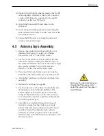
Make sure the cable jacket passes
through the PCB access slot to
protect the wires from the edge of
the PCB frame.

