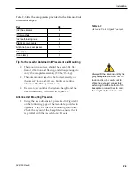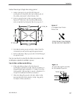
2. Drill four
3
⁄
8
" (10 mm) bolt holes. Mark a
3" (80 mm) diameter circle in the center of the
pattern and cut out to make a passage for the
cables to connect to the baseplate. Smooth the
edges of the hole to protect the cables.
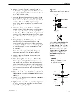
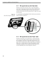
3. Place the foam seal in position on the mounting
surface with the hole centered over the cable
access cutout and the paper backing on the
bottom. Do not remove the paper backing at this
time. Align the seal with the vessel’s fore-and-aft
line and the small end pointed forward as shown
in Figure 2-2. Scribe a line all around the seal.
2-4
TracVision 4 Installation and Technical Manual
Figure 2-2
Baseplate/Foam Seal Orientation
(Bottom View)
Bow
RF1
RF2
J14 (data)
J13 (power)
Foam Seal
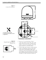
Figure 2-1
Antenna Unit Dimensions
21.00"
Max
54
cm
19.3"
49 cm
9.00ý
(22.9 cm)
9.00ý (22.9 cm)
4.50ý
(11.43 cm)
4.50ý
(11.43 cm)
4x 5/16ý (8 mm) THRU
19.3ý
(49 cm)
A template of the baseplate
mounting holes has been provided
in Appendix B.

