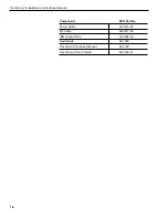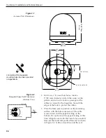
4. Remove and save the three screws holding the
radome to the baseplate. Carefully lift the radome
straight up until clear of the antenna assembly and
set it aside in a safe place.
5. Position the baseplate assembly in place over the
mounting holes and cable access. Ensure that all
holes line up and that the connectors are centered
over the cable access. Make any necessary
adjustments before seating the foam seal in place
permanently.
6. Clean the surface where the foam seal will be
placed. Remove the paper backing from the foam
seal to expose the contact cement. Lay the foam
seal in place, adhesive side down, and press down
firmly to bring the adhesive into full contact along
the bottom.
Ensure the narrow end points toward the
bow.
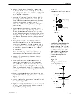
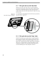
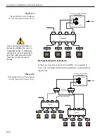
7. Bring the Data Cable, RF Cable(s), and Power
Cable up through the access hole and connect
them to the baseplate. Turn the connectors down
securely, but don’t use excessive force; finger-tight
is sufficient. Figure 2-3 illustrates the connector
assignments.
Do not
use teflon gel on the cable fittings as it
reduces signal strength at higher frequencies.
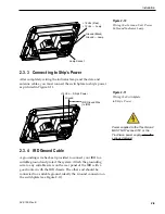
8. Remove the foam shipping restraint from the
Antenna Unit.
9. Place the baseplate over the holes drilled in the
foundation, ensuring the forward arrow points
toward the bow. Rotate the azimuth mechanism
plate to expose each mounting hole.
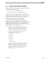
When rotating
the azimuth mechanism by hand, go slowly. Hitting the
stops with excessive force will damage the azimuth limit
switch.
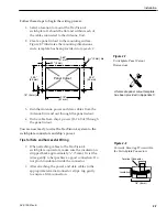
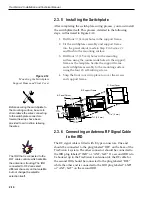
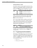
10. Place a flat washer from the kitpack on a bolt and
insert the bolt into its hole
from above
as shown in
Figure 2-4
.
11. Apply a flat washer and lock nut from underneath
as shown in Figure 2-4.
12. Tighten securely until the foam seal is compressed
as far as it will go and all four feet are bottomed
against the mounting surface.
2-5
Installation
54-0150 Rev. E
Figure 2-3
Baseplate Connector Assignments
RF1
RF2
J14 (data)
J13 (power)
Single IRD
Installation
Second IRD
Installation
The foam shipping restraint must
be removed before power is
applied. Save the foam for reuse
and be sure to install it whenever
the Antenna Unit is moved from
place to place. See Section 4.8,
“Preparation for Shipment,” for
instructions on preparing for
shipment.
Figure 2-4
Bolting the Antenna Unit to
the Deck (Side View)
Bolt
Flat Washer
Antenna Unit Base
Foam Seal
Deck
Flat Washer
Lock Nut

