2-6
TracVision 4 Installation and Technical Manual
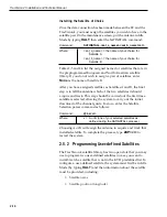
13. For European systems, please refer to
Section 2.2.1,
“Setting the Skew Angle.”
North American systems
may proceed to step 14.
14. Replace the radome over the baseplate. Align the
radome screw holes with the nut holders, insert
the screws and tighten. Install a protective plastic
screw cap from the kitpack over each screw.
Several spare protective caps are provided.
2.2.1 Setting the Skew Angle
(European
Systems Only)
The Antenna LNB skew angle must be adjusted to optimize
channel reception. Refer to your satellite service provider for the
proper skew angle for the selected satellite service and
geographical location.
Adjusting the LNB Skew Angle
1. Turn off the power to the Antenna Unit.
2. Remove the radome and set it aside.
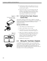
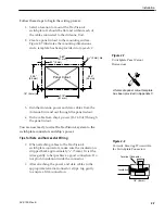
3. Loosen the two wing screws securing the LNB
within the choke feed as illustrated in Figure 2-5.
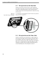
4. Refer to the LNB skew angle labels on the end of
the LNB and on the LNB choke feed (pictured in
Figure 2-6) and adjust the LNB as necessary to
match as closely as possible the skew angle
provided by your service provider.
5. Retighten the wing screws.
2.3
Wiring the TracVision 4 System
A switchplate has been provided to serve as the hub of the
TracVision 4 wiring (with the exception of the RF cable, which
will be connected to the IRD). This switchplate includes an
ON/OFF switch and a DB9 maintenance port for easy access to
the Antenna Unit’s software and diagnostics.
Figure 2-5
Adjusting the European
LNB Skew Angle
Figure 2-6
Skew Angle Labels

