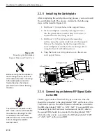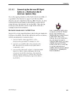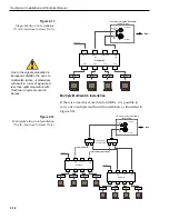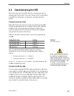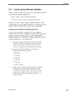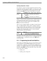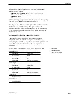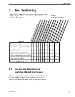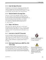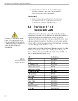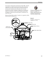
Based on this information, the data entered via the PC would look
like this, assuming that YOURSAT 101 would be Satellite A:
SATCONFIG,USER1,7,W,3,L
@DEBUGON
@SATCONFIG,A,98,11966,27500,34,0x0800,H,H,3
@SATCONFIG,A,98,11823,27500,34,0x0800,V,H,3
@SATCONFIG,A,98,00000,27500,34,0x0000,V,L,3
@SATCONFIG,A,98,00000,27500,34,0x0000,H,L,3
@SAVE,A
@DEBUGOFF
ZAP
2.6
Checking Out the System
To complete the TracVision 4 installation, it will be necessary to
verify that the system functions properly. Critical to ensuring that
the system is configured and operating properly is to check the
system startup routine to ensure that the system is operating
within normal parameters.
1. Connect the PC to the antenna as described in
Section 2.5.1, “Installing Your Selected Satellites.”
2. Open the terminal emulation software and establish
the following settings:
• 9600 baud
• no parity
• 8 data bits
• 1 start bit
• 1 stop bit
• no flow control
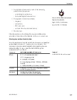
3. Apply power to the TracVision 4 system and allow
the system to complete full initialization. Data
should be scrolling on the PC display to identify
any system problems detected. If no data is seen,
recheck your connections and the terminal software
setup.
4. After completing the review of the startup and
operational routines, turn on the IRD and television
and check the channels on the selected satellites.
For European systems, view both horizontally and
vertically polarized channels, if possible.
5. When all checks are completed, shut down the
system.
2-20
TracVision 4 Installation and Technical Manual
A sample startup sequence has
been provided in Appendix F with
the typical ranges and responses
for the TracVision 4 during startup
and operation.
Be certain to fill out and submit the
warranty card to KVH to ensure
that your TracVision 4 is fully
covered under the 2-year parts and
1-year labor warranty.
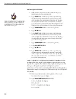
Avoid turning the vessel for 60
seconds after turning on the
antenna to allow the antenna gyro
to initialize properly.

