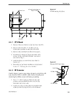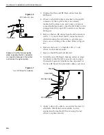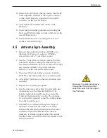
Antenna Gyro Calibration
1. With the PC connected to the maintenance port,
apply power to the antenna unit.
2. Type
HALT<cr
> while the system is performing
the limit switch initialization routine. The system
will complete the initialization function by finding
the azimuth and elevation switch limits and then
go to the home position. Record the 8-digital serial
number that was displayed in the startup message.
3. Type
DEBUGON<cr>
to enter Debug Mode.
4. Type
ZAP<cr>
.
5. Type
HALT<cr>
while the system is performing
the limit switch initialization routine. The system
will complete the initialization function by finding
the azimuth and elevation switch limits and then
go to the home position.
6. Type
DEBUGON<cr>
to enter Debug Mode.
7. Type
=CALGYRO<cr>
.
8. Type
ZAP<cr>
.
9. Type
HALT<cr>
while the system is performing
the limit switch initialization routine. The system
will complete the initialization function by finding
the azimuth and elevation switch limits and then
go to the home position.
Steps 10 through 12 will speed the antenna’s acquisition of the
satellite when GPS input to the antenna is not present. It is not
required to complete the Antenna Gyro replacement process but
doing so will speed acquisition and improve system
performance. If you are not entering the latitude and longitude as
described in Steps 10 through 12, continue to Step 13 to complete
the process.
10. Determine the latitude and longitude of the vessel
location to the nearest degree.
11. Type
GPS,AA,B,CCC,D<cr>
where
• AA = Latitude in degrees
• B = N or S
• CCC = Longitude in degrees
• D = E or W
4-8
TracVision 4 Installation and Technical Manual
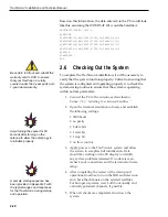
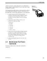
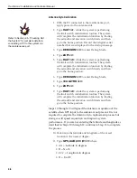
Refer to Section 2.6, “Checking Out
the System” for complete details in
connecting a PC to the system via
the maintenance port.

