background image

-1-

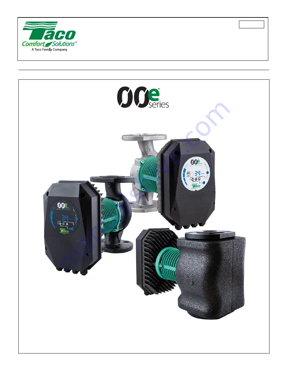
ECM High-Efficiency Circulators 

INSULATION SHELL

 INCLUDED

Installation & Operation Instructions Manual

VR15, VR20, VR25 & VR30

(ALL CIRCULATORS ARE AVAILABLE IN LOW, MEDIUM AND HIGH HEAD MODELS)

302-393

SUPERSEDES: New
Plant ID No. 001-5038

EFFECTIVE: August 2, 2021

Summary of Contents for 00e Series

Page 1: ...lators INSULATION SHELL INCLUDED Installation Operation Instructions Manual VR15 VR20 VR25 VR30 ALL CIRCULATORS ARE AVAILABLE IN LOW MEDIUM AND HIGH HEAD MODELS 302 393 SUPERSEDES New Plant ID No 001...

Page 2: ...nstruction 15 Section 2 Controller VFD Operation 16 12 Features 16 12 1 Specifications 17 12 2 BACnet Specifications 17 12 3 Modbus Specifications 17 12 4 Ethernet Specifications 17 12 4 Mode Selectio...

Page 3: ...e installation operation and control module for VR15 through VR 30 Low Medium and High head range of pumps Section 1 describes the installation and operation features Section 2 describes the control m...

Page 4: ...principale Respectez tous les codes de plomberie et lectriques locaux WARNING Hot surfaces can cause burns The motor can also reach temperatures that could cause injury AVERTISSEMENT Les surfaces chau...

Page 5: ...ironment To reduce potential abrasive damage a magnetic iron removal device is recommended to remove excessive iron oxide from the system fluid 8 PUMP INSTALLATION The 00e pump is protected with a dou...

Page 6: ...tly loosen the motor then rotate If all else fails completely remove the motor and reinstall in the desired configuration Ensure the Volute O Ring is placed in the volute between the rotor assembly an...

Page 7: ...on of the design of the pump Temporary air in the pump will generate noise that disappears after a short time Extended periods of dry running will activate an E10 low motor load error and in most case...

Page 8: ...s not require additional overload protection devices unless required by local electrical codes Power supply cabling should be capable of carrying rated power and be properly fused Grounding connection...

Page 9: ...umerical display shows OFF To turn the pump on press the key briefly 10 3 Pump Functions Key Short press Scrolling through parameters downwards not changing parameter values Scrolling through modes do...

Page 10: ...onal Pressure The pump maintains the pressure with relation to the current flow The pressure is equal to the set pressure Hset on the drawing at maximum power at 0 flow it is equal to HQ default 50 HQ...

Page 11: ...7 Minimum Speed Adjustment 1 Connect to the pump HTML Web Page 2 Open Pump Tab see below i Min Setpoint dropdown window 1 Adjustable between 10 and 100 of full speed in 10 increments 2 Select a for m...

Page 12: ...oth pumps connected via a CROSSOVER Ethernet cable The installation of a check valve is required on the discharge side of each pump installed at least 10 pipe diameters from the pump discharge Failure...

Page 13: ...pump After 10 to 15 seconds the standby pump should come on 3 5 IMPORTANT Ethernet cable installation recommendation 3 5 1 Due to the enclosure rating an Ethernet RJ 45 cable end will typically not f...

Page 14: ...9 2 1 Max Power W 270 480 680 370 560 820 560 810 1550 800 1380 1550 Rated Current A 1 2 2 1 2 9 1 7 2 4 3 6 2 5 3 5 6 6 3 5 6 6 6 Current Limit Max A 6 6 6 6 6 6 6 6 8 6 8 8 24V Supply Output Max cur...

Page 15: ...UL778 1004 1 508C CAN CSA C22 2 108 100 107 1 EMC 89 366EEC EN61000 LVD 73 23 EC EN60335 1 EN60335 2 51 Machine Safety 98 37 EC EN ISO 12100 Flange Connections Class 125 150 ANSI 4 bolt 11 4 Material...

Page 16: ...onnection configurations Not all functions can be used simultaneously on off 0 10 V relay output Modbus BACnet RTU Relay output Ethernet on off 0 10 Modbus BACnet RTU Ethernet Ethernet on off relay ou...

Page 17: ...odbus visual diagnostics LED2 Flashing yellow when data reception detected Combined OR with Ethernet ACT function Max number of Modbus devices 247 Limited by possible Modbus addresses to 247 1 8 nomin...

Page 18: ...g input common ground SET2 MAX Control signal 2 SET3 FB Control signal 3 NC Normally closed relay contact Opens when relay is active C Relay common contact NO NO Normally open relay contact Closes whe...

Page 19: ...terminals or cut No loose wiring permitted 13 2 Connection Examples If voltages over 24VAC DC are possible on NO C NC terminals Wires should be routed so no wire crosses the center barrier Relay cable...

Page 20: ...h the gland inlet and then crimped to a connector 14 CONTROL MODES AND PRIORITIES 14 1 Setting Priority Several signals will influence the pump operation For this reason settings have priorities as sh...

Page 21: ...ssible confusion use of night mode is discouraged while using external control 3 Only available when pump is bus controlled 4 Not available when pump is bus controlled 5 Multiple limits can be set Not...

Page 22: ...olar SET1 PWM in 0 Pump OFF SET2 PWM out status SET3 FB 10 5 V output can be used to supply SET1 and SET2 4 Mode 4 PWM Heating SET1 PWM in 100 Pump OFF SET2 PWM out status SET3 FB 10 5 V output can be...

Page 23: ...e the pump to max or minimum speed user selectable Contact Position Function Description RUN MAX Stop the pump The pump is stopped Start the pump The pump will run with internal set point Minimum curv...

Page 24: ...or Pump starts and stops on medium speed for pre and post purging IMPORTANT Mode value must not be set to MAX or Auto otherwise changes in the 0 10Vdc signal will not change the pump s performance Min...

Page 25: ...ead 15 of max head NOTE Min speed user adjustable to meet min flow requirements 3 to 10 V speed increases linearly to V Set 3 and Set 1 Closed decreasing of 0 10Vdc signal 10 to 3 V speed decreases li...

Page 26: ...ion Increase of 0 10Vdc signal 0 to 2 V pump off 2 to 3 V pump runs at min speed 25 of max speed or min head 15 of max head NOTE Min speed user adjustable to meet min flow requirements 3 to 10 V speed...

Page 27: ...signal 0 to 0 5 V pump runs at min speed 25 of max speed or min head 15 of max head NOTE Min speed user adjustable to meet min flow requirements 0 5 to 10 V speed increases linearly to V Set 3 and Set...

Page 28: ...ontrol using a separate digital signal Terminal Designation Signal Function SET1 RUN PWM in PWM input Signal frequency 100 Hz 10000 Hz 1000 Hz nominal Signal load 5 mA 4 6 mA internally limited Signal...

Page 29: ...12 pump standby 12 to 15 pump runs at min speed 20 of max speed or min head 10 of max head NOTE Min speed user adjustable to meet min flow requirements at 3 V 15 to 95 speed or head increases linearly...

Page 30: ...gnal 95 to 15 speed decreases linearly with change 15 to 7 pump runs on min speed 7 to 0 pump standby MODE 4 PWM Heating SET2 PWMout Status 0 PWM output interface in short circuit 2 5 Pump in standby...

Page 31: ...ion parameters power RPM head flow efficiency Relay settings External control inputs Current and previews error Pump statistics power consumption run time and other 7 When Mode 6 or Mode 7 is selected...

Page 32: ...ernet is NOT required Standard or crossover ethernet cables CAT 5 and above can be used IMPORTANT When connecting pump to pump for parallel applications a crossover ethernet cable must be used Due to...

Page 33: ...OT required d Enter the pumps IP Address or NetBIOS Name in the web browser i Default IP is 192 168 0 245 ii Default IP for a Lag or Back up pump in a parallel application is typically 192 168 0 246 e...

Page 34: ...pump is in standby and has a maximum wattage of 1550W shown in brackets Control Signals Mode switch setting and all external control input settings and actual values IMPORTANT This is where the actual...

Page 35: ...t applicable in Constant Speed Configuration This value is carried over to the max value in brackets on the Overview Tab Max RPM Dropdown sets the maximum speed IMPORTANT NOTE If an external speed con...

Page 36: ...mp Operation Always on and No Function Pump Fault is factory default Save All IMPORTANT Any changes made in this tab require the SAVE button be clicked for the changes to take effect Network Tab Netwo...

Page 37: ...e Overview and Pump pages Always click Save when changing settings Pump and Network If changing the main IP address it is very important to record and post the new IP address Look for network LEDs to...

Page 38: ...tp server on this address default 192 168 0 245 DHCP server provides lease for point to point connection cross over cable to computer for example Will disable itself if another DHCP server is found DH...

Page 39: ...Controller B AAC BACnet Application Specific Controller B ASC BACnet Smart Sensor B SS BACnet Smart Actuator B SA Name BACnet BIBB Read Property DS RP B Write Property DS WP B BACnet Interoperability...

Page 40: ...O 10646 UCS 2 ISO 10646 UCS 4 JIS X 0208 ANSI X3 4 Name BACnet BIBB Read Property DS RP B Read Property Multiple DS RPM B Write Property DS WP B Write Property Multiple DS WPM B Subscribe COV DS COV B...

Page 41: ...I 9 QMax GPM Maximum pump flow AI 10 PMax W Rated pump power AI 11 RPMMax W Maximum motor speed AI 12 Operating Hours h Time active not implemented 0 AI 13 Energy Consumed kWh Total electrical energy...

Page 42: ...ximum speed 0 No 1 Yes This flag is set when power or speed is over 95 of rated maximum 17 11 Binary Outputs ObjectType 4 Instance Object Name Unit Description BO 0 Remote Access Enable Control bit th...

Page 43: ...a limited length passive tap Schematic example is in Figure 6 Figure 6 Example of Modbus network Typically only one Lead pump device is connected to the serial bus and one or several lags are also con...

Page 44: ...RS 485 wiring should be externally terminated if needed For short wiring and or low baud rate interface can operate without termination However it is recommended that termination 100 150 ohm resistor...

Page 45: ...ne Word registers Some are bit interpreted while others are combined for a 32 bit value VR control registers Registers in this block are read with either function codes 0x03 or 0x04 They can be writte...

Page 46: ...57600 baud 005 008 RESERVED 009 Parity 0 2 1 Parity setting to be used for communication 0 No parity 1 Even parity default 2 Odd parity 010 StopBits 1 2 2 Stop bits used for communication 2 stop bits...

Page 47: ...mmunication 2 stop bits will only be used when Parity is set to 0 1 1 stop bit default 2 2 stop bits 017 Relay2Control 0 2 1 Configures module relay output 0 indicates fault 1 indicates pump ready 2 i...

Page 48: ...ntRPM 1 ConstantRPM 3 ConstantHead 4 ConstantHead 5 ConstantHead 6 ProportionalHead 128 AutoHeadMode NOTE values outside this range reserved 103 Operation Mode RESERVED 104 SetPoint 0 10000 Sets desir...

Page 49: ...is set when speed falls below 1 3 of rated maximum 202 RESERVED TBD 203 ControlMode Indicates the actual control mode 0 ConstantRPM 1 ConstantRPM 3 ConstantHead 4 ConstantHead 5 ConstantHead 6 Proport...

Page 50: ...W Total power consumption of the system 313 PowerLO 0 232 1 W Total power consumption of the system 314 317 RESERVED 318 CircuitTemp 5500 16000 0 01 C Power electronics hotspot temperature 319 MotorT...

Page 51: ...lectrically check motor electrical connections Check motor mechanically for external water leaks build up of stator condensation or thermal damage Misalignment of the impeller eye and volute seal ring...

Page 52: ...e of the volute Misalignment will occur during the motor alignment process If OK perform a hard reset power pump off on E52 Excessive motor temperature Motor is too hot Pump will not run until the mot...

Page 53: ...5 140 13 7 18 3 9 1 4 6 FLOW GPM FLOW liter min 132 265 400 530 HEAD FT HEAD m VR15H VR15M VR15L 60 45 30 15 0 0 50 100 150 200 FLOW GPM FLOW liter min HEAD FT HEAD m 13 7 18 3 9 1 4 6 189 378 568 757...

Page 54: ...5 35 17 5 0 0 75 150 225 300 16 21 3 10 7 5 3 FLOW GPM FLOW liter min 284 568 850 1135 HEAD FT HEAD m VR25M VR25L VR25H 70 52 5 35 17 5 0 0 100 200 FLOW GPM FLOW liter min 300 400 HEAD FT 10 7 5 3 37...

Page 55: ...55 VR15 L M H VR20 L M H...

Page 56: ...al or consequential damages so these limitations or exclusions may not apply to you 2021 Taco Inc will repair or replace without charge at the company s option any product or part which is proven defe...

Reviews: