


BCU 560, BCU 565 · Edition 02.16
45
Profinet > GSD file for PLC configuration > Modules for cyclic data exchange
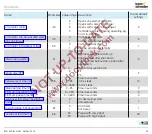
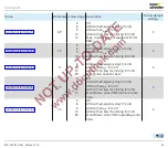
“Burner 1 flame signal” module (device
➔
controller) – slot 2
The flame signal is transferred from the BCU to the PLC as an
analogue value using this module. The flame signal occupies
one byte with values from 0 to 255 (= flame signal from 0 to
25.5 µA).
Bit Byte n
Data type Format
Value
0
Burner 1 flame signal
Byte
DEC
0 – 255
(0 – 25.5 μA)
1
2
3
4
5
6
7
“Status signal” module (device
➔
controller) – slot 4
This module transfers the status signals from the BCU to
the PLC. The status signals occupy one byte (0 to 255). Every
status signal is allocated a code. The allocation is described
in the code table “BCU56x_GSD_Codetabelle.xlsx”.
Bit Byte n
Data type Format
Value
0
Status signals
Byte
DEC
0 – 255
(see
code table “BCU56x_
GSD_Codetabelle.
xlsx” at
www.docuthek.com)
1
2
3
4
5
6
7
“Fault and warning signals” module (device
➔
controller) – slot 5
The fault and warning signals are transferred from the BCU to
the PLC using this module. The fault and warning signals oc-
cupy one byte each (0 to 255).
The allocation of the output codes to the fault and warning sig-
nals is described in the code table “BCU56x_GSD_Codetabelle.
xlsx”. The same allocation table applies to the fault signals
and the warning signals.
Bit Byte n
Data type Format
Value
0
Fault signals
Byte
DEC
0 – 255
(see
code table “BCU56x_
GSD_Codetabelle.
xlsx” at
www.docuthek.com)
1
2
3
4
5
6
7
Bit Byte n+1
Data type Format
Value
0
Warning signals
Byte
DEC
0 – 255
(see
code table “BCU56x_
GSD_Codetabelle.
xlsx” at
www.docuthek.com)
1
2
3
4
5
6
7
▼


