


BCU 560, BCU 565 · Edition 02.16
20
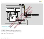
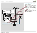
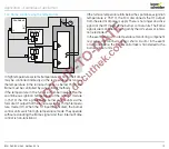
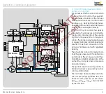
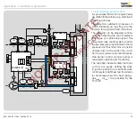
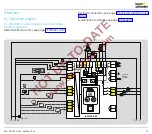
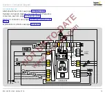
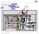
3 .1 .5 BCU 565 . .F1
Alternative flame control, see page 22 (Flame control).
Detailed connection diagrams for actuators and frequency
converters, see from page 78 (Capacity control)
Electrical connection, see page 106 (Project planning infor-
mation)
Explanation of symbols, see page 126 (Legend)
Function > Connection diagram
1
2
3
46
45
48
47
65
66
67
68
49
50
51
17
18
37
38
13
14
15
5 6
9
11 12
10
N
L1
V1
V2
V3
max. 1 A;
24 V DC,
250 V AC
BCU 565..F1
7
3,15AT
µC
88
P70
P70
P73
P72
P72
c
62 61
ϑ
0 V
+24 V
41
42
24V
DC
44
HT
p
u
2
GZL
PZL
P
c
A
PZL
PDZ
PZL
PDZ
P72
P71
mA
52
P69
(P40 = 2/3) => 51
53
54
55
56
I
Z
Air
min
Air
0.6 × I
N


