


BCU 560, BCU 565 · Edition 02.16
109
Project planning information > Electrical connection
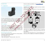
13 .3 .3 UVD control
1
2
3
46
45
65
66
67
68
49
50
51
17
18
37
38
13
14
15
N
L1
V1
V2
V3
max. 1 A;
24 V DC,
250 V AC
BCU 560..F0
3,15AT
µC
88
P70
P69
P70
P73
P72
P72
c
c
ϑ
0 V
+24 V
41
42
24V
DC
HT
LDS
p
u
2
GZL
PZL
P
5 6
9
11 12
10
7
62 61
I
Z
(BCU 560..F3 only)
(BCU 560..F3
only)
0.6 × I
N
An additional voltage supply of 24 V DC is required to operate
the UV sensor for continuous operation UVD 1 in conjunction
with burner control unit BCU 560 or BCU 565. The 24 V DC
voltage supply and the 0 – 20 mA current output of the UV
sensor must be wired separately.
The 0 – 20 mA current output is not required for normal opera-
tion. The 0 – 20 mA current output can only be used to display
the flame signal. If it is used for the display in a control room for
example, then the cable to the control room must be screened.


