2
INSTALLATION
24
OPTIWAVE 7300 C
www.krohne.com
04/2009 - 4000050002 - QS OPTIWAVE 7300 R05 en
•
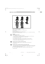
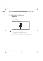
Remove the o-rings from the plastic sachet supplied with the device. Put an o-ring
4
into the
groove at the top of each antenna extension.
•
Attach the antenna extensions
1
below the flange.
•
Attach the antenna
2
.
•
Make sure the antenna extensions are fully engaged.
•
Use a 3 mm Allen wrench to tighten the locking screws
3
.
•
If you attach more or less extensions than were initially ordered, change the antenna
extension value in the program mode. Use the display screen or PACTware
™
.
i
Antenna extension = antenna extension length x number of extensions
•
If you attach more extensions than were initially ordered, change the blocking distance value
in the user interface.
i
Minimum blocking distance = antenna (antenna extension length x number of
extensions) + 0.1 m / 4
¨
2.9.4 How to turn or remove the signal converter
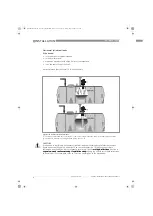
How to turn the signal converter
•
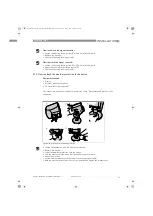
Loosen the housing locking screw
1
with a 5 mm Allen wrench.
•
Turn the housing to the correct position.
•
Tighten the housing locking screw.
INFORMATION!
The converter turns 360
°
. Remove the signal converter before you lift the device with a hoist.
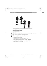
Figure 2-22: How to turn or remove the signal converter
Tool: 5 mm Allen wrench
CAUTION!
If you remove the housing, put a cover on the wave guide hole in the flange assembly
2
.
QS_OPTIWAVE7300_en_090528_4000050002_R05_web.book Page 24 Friday, May 29, 2009 4:01 PM


