5
TECHNICAL DATA
36
OPTIWAVE 7300 C
www.krohne.com
04/2009 - 4000050002 - QS OPTIWAVE 7300 R05 en
Installation conditions
Process connection size
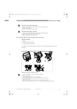
The process connection should be larger than the antenna diameter.
If the process connection on the device is smaller than the antenna, either:
- provide the means to adapt the device to a larger process connection on the tank
(for example, a plate with a slot), or
- use the same process connection, but remove the antenna from the device before
installation and fit it from inside the tank.
Process connection position
Make sure that there are not any obstructions directly below the process
connection for the device.
Dimensions and weights
Refer to "Technical data: Dimensions and weights" in the Handbook
Materials
Housing
Standard: Aluminium
Option: Stainless steel (1.4404 / 316 L)
Wetted parts, including antenna
Standard for Horn antenna: Stainless steel (1.4404 / 316L)
Option for Horn antenna: Hastelloy
®
C-22 (2.4602)
1
Drop antenna: PTFE; PP - a PP or PTFE flange plate option is also available
Process fitting
Standard: Stainless steel (1.4404 / 316L) - a PP or PTFE flange plate option is also
available for Drop antenna
Option: Hastelloy
®
C-22 (2.4602)
Gaskets (and o-rings for the
sealed antenna extension option)
FKM/FPM (-40
…
+200
°
C / -40
…
+390
°
F); Kalrez
®
6375 (-20
…
+200
°
C / -4
…
+390
°
F);
EPDM (-40
°
C
…
+150
°
C / -40
…
+300
°
F)
2
Feedthrough
Standard: PEI (-40...+200
°
C / -40...+390
°
F)
Option: Metaglas
®
(-30...+200
°
C / -22...+390
°
F - for horn antennas only)
3
Weather protection (Option)
Stainless steel (1.4301 / 304)
Process connections
Thread
G 1
½
; 1
½
NPT
Flange version
Flange version
Flange version
Flange version
EN
DN40
…
150 in PN40 / PN16; others on request
ASME
1
½¨…
8
¨
in 150 lbs / 300 lbs; others on request
JIS
40
…
100A in 10K; others on request
Electrical connections
Power supply
Terminals output 1 - Non-Ex / Ex i:
Terminals output 1 - Non-Ex / Ex i:
Terminals output 1 - Non-Ex / Ex i:
Terminals output 1 - Non-Ex / Ex i:
14
…
30 VDC; min./max. value for an output of 22 mA at the terminal
Terminals output 1 - Ex d:
Terminals output 1 - Ex d:
Terminals output 1 - Ex d:
Terminals output 1 - Ex d:
20
…
36 VDC; min./max. value for an output of 22 mA at the terminal
Terminals output 2 - Non-Ex/ Ex i/ Ex d:
Terminals output 2 - Non-Ex/ Ex i/ Ex d:
Terminals output 2 - Non-Ex/ Ex i/ Ex d:
Terminals output 2 - Non-Ex/ Ex i/ Ex d:
10
…
30 VDC; min./max. value for an output of 22 mA at the terminal (additional
power supply needed - output only)
Cable entry
M20x1.5;
½
NPT
G
½
(not for FM- and CSA-approved devices)
M25x1.5 (for stainless steel housings only)
Cable gland
Standard: none
Options: M20x1.5 (for non-Ex and Ex -approved devices with M20x1.5 and M25x1.5
cable entries); others are available on request
Cable entry capacity (terminal)
0.5
…
1.5 mm
²
QS_OPTIWAVE7300_en_090528_4000050002_R05_web.book Page 36 Friday, May 29, 2009 4:01 PM


