2
INSTALLATION
14
OPTIWAVE 7300 C
www.krohne.com
04/2009 - 4000050002 - QS OPTIWAVE 7300 R05 en
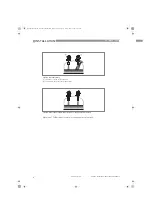
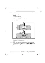
Installation in tanks containing one liquid and foam
•
Drill a pressure equalization hole in the stilling well above the maximum level.
•
Deburr the hole.
Installation in tanks containing one liquid or more without foam
•
Drill a pressure equalization hole in the stilling well above the maximum level of the top liquid.
•
Drill a liquid circulation hole in the stilling well above the maximum level of the interface (if
there is more than 1 liquid in the tank).
i
These holes help the liquid to move freely between the stilling well and the tank.
•
Deburr the holes.
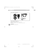
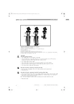
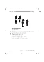
Figure 2-11: Installation recommendations for stilling wells
1
Basic requirements for a stilling well
2
Recommendations for tanks that have one or more liquids without foam
3
Air circulation hole
4
Maximum level of the liquid
5
Liquid circulation hole above the maximum level of the interface
6
Clearance between the antenna and the wall of the stilling well <2.5 mm / 0.1
¨
for a high-dielectric constant liquid
7
Sudden change in well diameter <1 mm / 0.04
¨
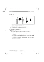
CAUTION!
Installation requirements
•
The stilling well must be electrically conductive.
•
The inside diameter of the bypass chamber must not be more than 5 mm / 0.2
¨
over the
diameter of the antenna (for a high-dielectric constant liquid).
•
The stilling well must be straight.
•
The stilling well must have a surface roughness of
±
0.1 mm / 0.004
¨
or better.
•
There must be no sudden changes in internal diameter greater than 1 mm / 0.04
¨
.
•
The bottom of the stilling well must be open.
QS_OPTIWAVE7300_en_090528_4000050002_R05_web.book Page 14 Friday, May 29, 2009 4:01 PM


