background image


Kramer Electronics Ltd. 

24 

14 

TROUBLESHOOTING   

If the recommended actions still do not result in satisfactory operation, please consult your Kramer Dealer.  
Before seeking technical assistance, if the problem is image related, please try to find out the screen resolution 
and refresh rate being used from the computer and if the problem only affects one particular resolution. 
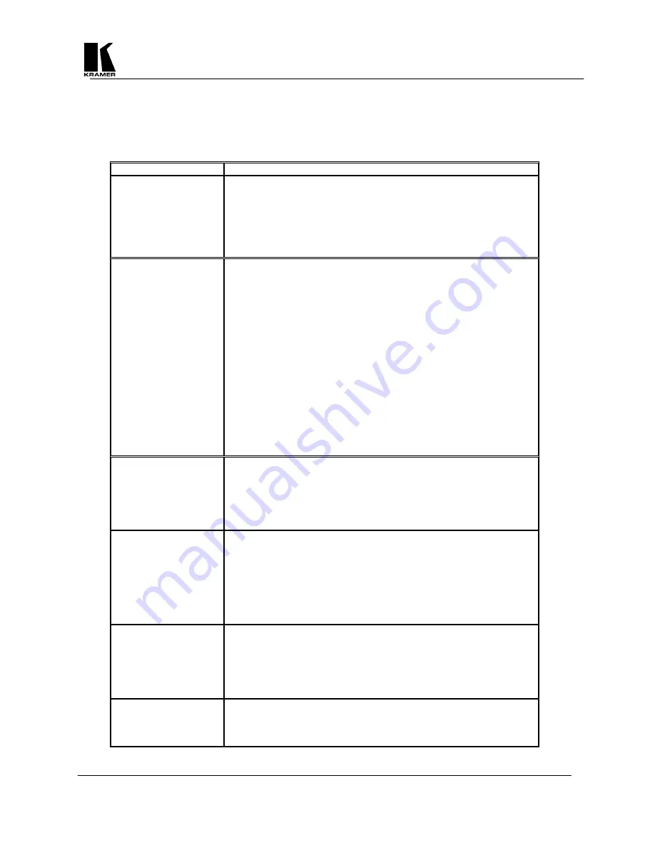
 

Problem Remedy 


 The picture on the video 
display is black and 
white. 

1.  If you are using the S-Video or Composite outputs, then make 

sure that all these cables are connected correctly.   

2.  Make sure that the Scan Converter is adjusted to the right video 

standard PAL/NTSC (The procedure to change this is found 
elsewhere in this manual).  

3.  Ensure that the color controls on your TV or video monitor are all 

set correctly. 

There is no picture on 
the video monitor. 

1.  If you're using the unit with a laptop computer, make sure the 

laptop is set to enable an external display device.  Some laptops 
automatically detect external video connections, but others will 
need setting up to do so.  This is often accomplished by pressing 
two keys simultaneously on the keyboard. 

2.  If the Power LED on the Scan Converter is off, ensure that the 

proper AC Power is being supplied to the unit and check the fuse 
(The procedure located elsewhere in this manual). 

3.  If the Power LED is on: a) Check that the monitor output from the 

computer is connected to the Scan Converter’s VGA IN 
connector, b) Check that the output you are using from the Scan 
Converter is also connected at the unit and the video monitor, and 
c) Check that your video monitor is switched on and set to the 
correct input (AUX or A/V is selected), also make sure that the 
Brightness and Contrast on the video monitor are set correctly. 

4.  Don’t forget that when the Scan Converter is in the YUV Mode, 

all other video outputs will be blanked out. 

There is no picture on 
the computer monitor. 

1.  Check that the VGA output from the computer is connected to the 

Scan Converter’s VGA IN connector.   

2.  Check that the computer monitor is connected to the VGA OUT 

connector on the back of the Scan Converter.  

3.  Check that your computer monitor is turned on and the Brightness 

and Contrast are set correctly. 

The display on the TV 
has a huge border around 
it. 

1.  This usually means that you are using a laptop computer at a 

resolution lower than the laptop's own screen.   When this 
happens, the laptop fits the smaller resolution into the larger with 
a border around the edge.   

2.  Since the laptop's screen is of a fixed resolution, the only two 

solutions are: a) change the resolution you're running at to match 
the laptop's own internal screen, or b) disable the laptop's own 
screen, so you just see the image on the video monitor. 

The unit does not 
respond to the Infrared 
remote control. 

1.  Ensure that there are batteries in the Remote Control unit are 

correctly inserted and that they have enough charge left.   

2.  Make sure that there is no obstruction in front of the Scan 

Converter's Front Panel Infrared Window.   

3.  Ensure that the Scan Converter is set for control from the IR unit 

(The procedure to change this is found elsewhere in this manual). 

There is excessive 
flicker on the TV. 

1.  Try using a different Flicker Reduction Filter setting (The 

procedure to change this is found elsewhere in this manual).   

2.  Turning the contrast down and the brightness up on the video 

monitor can also have a large effect on flicker.  

Summary of Contents for VP-704SC

Page 1: ...KRAMER ELECTRONICS LTD KRAMER ELECTRONICS Ltd USER MANUAL SCAN CONVERTERS Models VP 704SC VP 705SC VP 706SC IMPORTANT Before proceeding please read paragraph entitled Unpacking and Contents...

Page 2: ...ode 8 7 2 Adjust Menu 9 7 3 Studio Genlock Mode 10 7 4 Screen Size Mode 10 7 5 Zoom Mode 11 7 6 Manual Set Mode 11 8 ADVANCED MENUS FEATURES 12 8 1 Advanced Menu 13 8 2 Engineering Menu 15 9 CONTROL A...

Page 3: ...important to understand the overall process of scan conversion and its inherent limitations 1 2 Factors Affecting Quality of Results There are many factors affecting the quality of results when comput...

Page 4: ...S Video on 4 Pin Mini DIN RGBS on BNCs YUV shares RGBS BNCs Composite Video on BNC S Video on 4 Pin Mini DIN RGBS on BNCs YUV shares RGBS BNCs Genlock Signal N A Composite or Blackburst 1V P P Composi...

Page 5: ...Converter and related hardware Below is a drawing of the rear panel The VP 704SC does not have the GL IN and GL OUT connectors B B Y VS G Y HS CS R R Y CV SV OUT OUTPUTS VGA OUT VGA IN RS232 POWER 10...

Page 6: ...nal to the BNC connector marked GL IN A loop through output is available at the GL OUT BNC connector for connection to other devices Note If no loop through is required you must connect the supplied 7...

Page 7: ...will be described in a moment but is normally used to decrease or de select the currently displayed option or feature Freeze Button This is another dual purpose button but normally used to increase or...

Page 8: ...option The OS US Button toggles between Underscan and Overscan Underscan Mode sometimes know as Compress mode will leave a border around the image Overscan Mode has no border and the displayed image...

Page 9: ...refining and the AutoTrack function allows the unit to search for the image edges to improve on this Before running the AutoTrack function set the computer so that it is displaying a light colored bac...

Page 10: ...a lock with Phase adjustment is most accurate and has the least jitter when SC Phase is set nearest to 0 degrees 7 3 4 H Phase Horizontal Sync Phase Adjustment This value will adjust the relative diff...

Page 11: ...therwise the user may be able to Pan to areas of the computer image that are completely empty The Panning settings are remembered when Zoom is subsequently turned off This feature is useful in many tr...

Page 12: ...Subsequent pressing of the Menu Button will select the next Advanced feature to alter Any of these new settings can be stored using the Store Settings Multi Buttons hold MENU and the Button together f...

Page 13: ...OUT connector However if necessary it is possible to turn the termination off For example if the Scan Converter does not sense that the monitor is attached this would result in double termination of...

Page 14: ...ync on Pin 13 and Positive or Negative Vertical Sync on Pin 14 Grn Sy Negative Composite Sync present on Green Pin 13 Negative Composite Sync on Pin 13 Pin 15 Negative Composite Sync on Pin 15 8 1 12...

Page 15: ...DAC Ref Output Video Level The Digital to Analog Converter DAC changes the digital data output from the processing circuit into an analog form that can be displayed on a standard video monitor or TV A...

Page 16: ...9 1 Introduction This Scan Converter has been designed for ease of use and you should find most of the controls simple to understand and apply Some features such as Brightness Control require more tha...

Page 17: ...etting to the non volatile memory you may want to do a Factory Reset as described elsewhere in this manual 9 2 2 Store Button This button is used for saving new settings to the Scan Converter s memory...

Page 18: ...people from adjusting the unit without the Remote Control Note this feature is intended for use when other users should not disturb the settings of the unit 9 2 10 Level Button This button is not used...

Page 19: ...all the Standard Serial Mouse driver Use the Remote Control s four Arrow Buttons to move your mouse pointer around the screen L CLICK left click has the same function as a single left click of a stand...

Page 20: ...ter Of course delays due to slow baud rates will play a greater part than this The Scan Converter input buffer is limited to 32 bytes so do not send any more characters including CR LF etc than this F...

Page 21: ...H Soften Off On On Soften image horizontally ID Restrict n Restricts RS 232 control only to those units which have RS 232 ID already set to this value Image Freeze Off On On Image Frozen Do not adjus...

Page 22: ...section is to help you exploit some of these applications and functions to get the best possible results Hints Tips 1 Use S Video in preference to Composite Video if your equipment has such an input S...

Page 23: ...with different screen resolution settings which will optimize your Scan Converter to its full potential 9 Freeze function This function is useful if you wish to change to another image or layout while...

Page 24: ...and set to the correct input AUX or A V is selected also make sure that the Brightness and Contrast on the video monitor are set correctly 4 Don t forget that when the Scan Converter is in the YUV Mo...

Page 25: ...limited to avoid them interfering with each other 2 Using good quality video cable will help towards reducing this affect How do I use the unit with a VCR 1 Connect one of the Scan Converter s video o...

Page 26: ...including adjustment of user controls or programming These costs are the responsibility of the Kramer dealer from whom the product was purchased 3 Shipping charges HOW YOU CAN GET WARRANTY SERVICE 1...

Page 27: ...have prior approval This may be obtained from your dealer 16 COMPLIANCE NOTICE This equipment has been tested to determine compliance with the requirements of EN 55022 CE emissions standards Class B E...

Page 28: ...l 972 2 654 4000 Fax 972 2 653 5369 e mail kramerel netvision net il The list of Kramer distributors appears on our web site www kramerelectronics com From the web site it is also possible to e mail f...

Reviews: