background image


Kramer Electronics Ltd. 

 If there is no picture on the video monitor, go to the Troubleshooting section.  One possible cause is that the 
YUV output is enabled, which will blank out all other video outputs.  This is also covered in the Advanced 
Features section. 


ABOUT THE SCAN CONVERTER 

There are 3 ways to control the Scan Converter: 


By the Buttons on the Front Panel in conjunction with the LCD (Liquid Crystal Display). 


By the Infrared Remote Control unit. 


Directly from the computer via the RS-232 Serial Port. 

Each control method has its own section of this manual to describe the operation.  
 
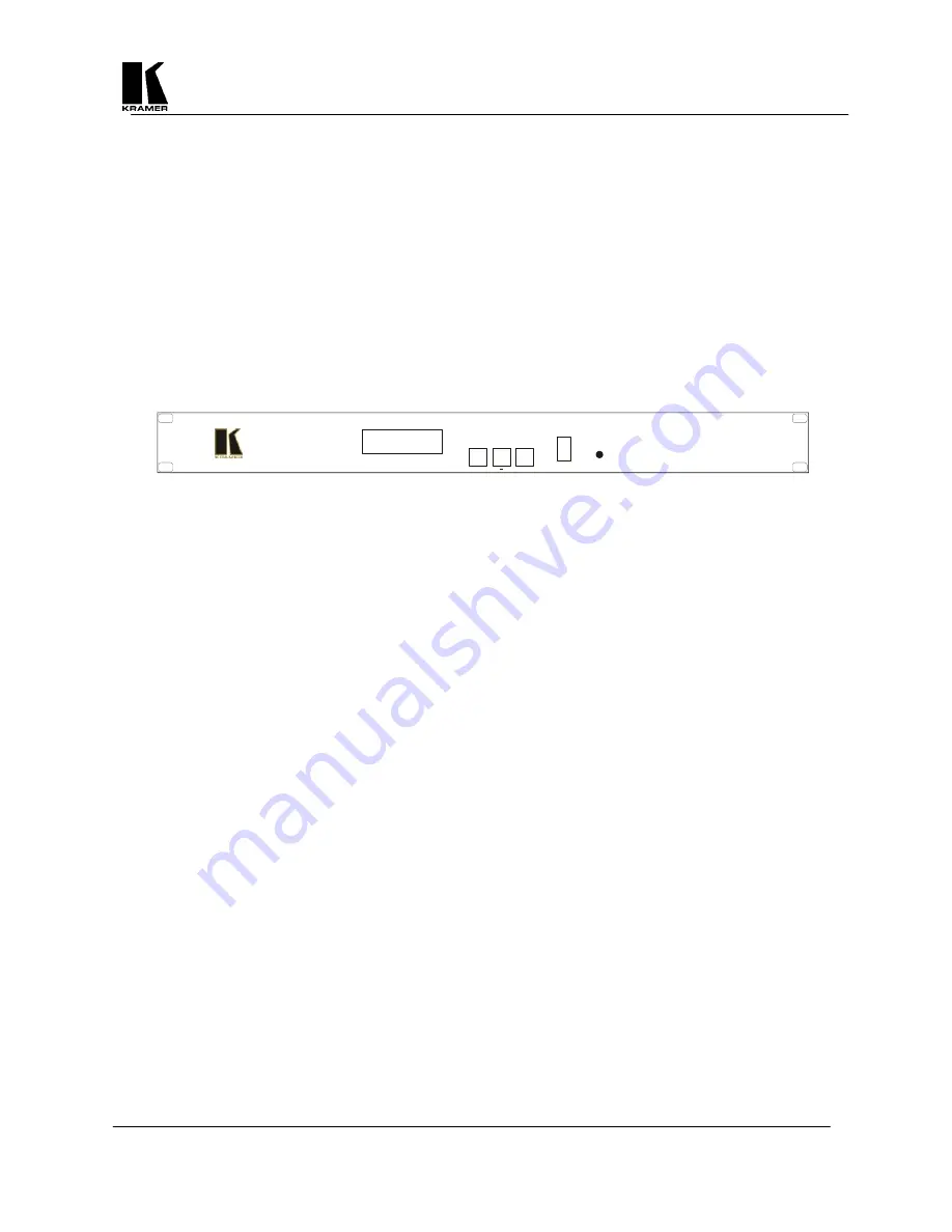
Shown below is a diagram that indicates the main features of the front panel of the VP-706SC.  All three Scan 
Converter models appear the same and their basic operation is identical.   
 

MENU

+

OS/US

FREEZE

VP-706SC

Digital Scan  Converter

IR

POWER

KRAMER  VP-706SC


LCD 

- The top line of the liquid crystal display (LCD) always indicates the current mode of the Scan 

Converter.  At power-up, this will be the 'Status' mode, but will change, depending on what the user 
wants the unit to do.  The bottom line always indicates the value that is or will be adjusted by the various 
control methods 


Power On LED 

– When the Scan Converter is powered up, the button labeled POWER will illuminate 

green.    


Menu Button

 – This is used to initiate Front Panel control of the unit and select the various options and 

features to change. 


OS/US (-) Button

 – This is a dual-purpose button that will be described in a moment, but is normally 

used to decrease (or de-select) the currently displayed option or feature. 


Freeze (+) Button

  – This is another dual-purpose button, but normally used to increase (or set) the 

currently displayed option or feature. 


Audible Indicator

 – The internal sounder is used to confirm that a setting has changed, and to indicate 

that the Scan Converter is saving the settings to non-volatile memory.  You will hear it regularly during 
normal use, but it can be disabled if needed. 

6.1 Quick-Set 

Buttons 

These are the dual-purpose buttons described earlier and only function when in Status mode (i.e. the top line of 
the LCD says 'Status').  They are provided for quick access to certain often-used functions - i.e. Toggling 
Underscan /Overscan and Freeze On/Off. 

6.2   Special Button Usage on Power-up 

Certain buttons can be held down when applying power to the unit, to perform certain functions: 


Factory Reset –

 Hold down both the OS/US and Freeze Buttons when turning the unit on. This will 

reset the unit to Factory Settings (and set the unit into NTSC video mode). It should only be used if the 
unit's settings give an invalid output that the user cannot exit from, as all user-settings will be lost.  

Note

use this procedure as a last resort. 


Set to NTSC Mode

 – This is done by holding the OS/US Button down when turning on the unit.  This 

changes the non-volatile PAL/NTSC setting to NTSC, and will be remembered even when power is 
removed. 


Set to PAL Mode

 – This is done by holding the Freeze Button down when turning on the unit.  This 

changes the non-volatile PAL/NTSC setting to PAL, and will be remembered even when power is 
removed. 


Summary of Contents for VP-704SC

Page 1: ...KRAMER ELECTRONICS LTD KRAMER ELECTRONICS Ltd USER MANUAL SCAN CONVERTERS Models VP 704SC VP 705SC VP 706SC IMPORTANT Before proceeding please read paragraph entitled Unpacking and Contents...

Page 2: ...ode 8 7 2 Adjust Menu 9 7 3 Studio Genlock Mode 10 7 4 Screen Size Mode 10 7 5 Zoom Mode 11 7 6 Manual Set Mode 11 8 ADVANCED MENUS FEATURES 12 8 1 Advanced Menu 13 8 2 Engineering Menu 15 9 CONTROL A...

Page 3: ...important to understand the overall process of scan conversion and its inherent limitations 1 2 Factors Affecting Quality of Results There are many factors affecting the quality of results when comput...

Page 4: ...S Video on 4 Pin Mini DIN RGBS on BNCs YUV shares RGBS BNCs Composite Video on BNC S Video on 4 Pin Mini DIN RGBS on BNCs YUV shares RGBS BNCs Genlock Signal N A Composite or Blackburst 1V P P Composi...

Page 5: ...Converter and related hardware Below is a drawing of the rear panel The VP 704SC does not have the GL IN and GL OUT connectors B B Y VS G Y HS CS R R Y CV SV OUT OUTPUTS VGA OUT VGA IN RS232 POWER 10...

Page 6: ...nal to the BNC connector marked GL IN A loop through output is available at the GL OUT BNC connector for connection to other devices Note If no loop through is required you must connect the supplied 7...

Page 7: ...will be described in a moment but is normally used to decrease or de select the currently displayed option or feature Freeze Button This is another dual purpose button but normally used to increase or...

Page 8: ...option The OS US Button toggles between Underscan and Overscan Underscan Mode sometimes know as Compress mode will leave a border around the image Overscan Mode has no border and the displayed image...

Page 9: ...refining and the AutoTrack function allows the unit to search for the image edges to improve on this Before running the AutoTrack function set the computer so that it is displaying a light colored bac...

Page 10: ...a lock with Phase adjustment is most accurate and has the least jitter when SC Phase is set nearest to 0 degrees 7 3 4 H Phase Horizontal Sync Phase Adjustment This value will adjust the relative diff...

Page 11: ...therwise the user may be able to Pan to areas of the computer image that are completely empty The Panning settings are remembered when Zoom is subsequently turned off This feature is useful in many tr...

Page 12: ...Subsequent pressing of the Menu Button will select the next Advanced feature to alter Any of these new settings can be stored using the Store Settings Multi Buttons hold MENU and the Button together f...

Page 13: ...OUT connector However if necessary it is possible to turn the termination off For example if the Scan Converter does not sense that the monitor is attached this would result in double termination of...

Page 14: ...ync on Pin 13 and Positive or Negative Vertical Sync on Pin 14 Grn Sy Negative Composite Sync present on Green Pin 13 Negative Composite Sync on Pin 13 Pin 15 Negative Composite Sync on Pin 15 8 1 12...

Page 15: ...DAC Ref Output Video Level The Digital to Analog Converter DAC changes the digital data output from the processing circuit into an analog form that can be displayed on a standard video monitor or TV A...

Page 16: ...9 1 Introduction This Scan Converter has been designed for ease of use and you should find most of the controls simple to understand and apply Some features such as Brightness Control require more tha...

Page 17: ...etting to the non volatile memory you may want to do a Factory Reset as described elsewhere in this manual 9 2 2 Store Button This button is used for saving new settings to the Scan Converter s memory...

Page 18: ...people from adjusting the unit without the Remote Control Note this feature is intended for use when other users should not disturb the settings of the unit 9 2 10 Level Button This button is not used...

Page 19: ...all the Standard Serial Mouse driver Use the Remote Control s four Arrow Buttons to move your mouse pointer around the screen L CLICK left click has the same function as a single left click of a stand...

Page 20: ...ter Of course delays due to slow baud rates will play a greater part than this The Scan Converter input buffer is limited to 32 bytes so do not send any more characters including CR LF etc than this F...

Page 21: ...H Soften Off On On Soften image horizontally ID Restrict n Restricts RS 232 control only to those units which have RS 232 ID already set to this value Image Freeze Off On On Image Frozen Do not adjus...

Page 22: ...section is to help you exploit some of these applications and functions to get the best possible results Hints Tips 1 Use S Video in preference to Composite Video if your equipment has such an input S...

Page 23: ...with different screen resolution settings which will optimize your Scan Converter to its full potential 9 Freeze function This function is useful if you wish to change to another image or layout while...

Page 24: ...and set to the correct input AUX or A V is selected also make sure that the Brightness and Contrast on the video monitor are set correctly 4 Don t forget that when the Scan Converter is in the YUV Mo...

Page 25: ...limited to avoid them interfering with each other 2 Using good quality video cable will help towards reducing this affect How do I use the unit with a VCR 1 Connect one of the Scan Converter s video o...

Page 26: ...including adjustment of user controls or programming These costs are the responsibility of the Kramer dealer from whom the product was purchased 3 Shipping charges HOW YOU CAN GET WARRANTY SERVICE 1...

Page 27: ...have prior approval This may be obtained from your dealer 16 COMPLIANCE NOTICE This equipment has been tested to determine compliance with the requirements of EN 55022 CE emissions standards Class B E...

Page 28: ...l 972 2 654 4000 Fax 972 2 653 5369 e mail kramerel netvision net il The list of Kramer distributors appears on our web site www kramerelectronics com From the web site it is also possible to e mail f...

Reviews: