


Kramer Electronics Ltd.
23
the limited number available on the TV. So lowering your graphic resolution will help improve image
quality. (Remember to run AutoTrack after you change the resolution).
6. If you experience line dropping, use a higher Flicker Reduction setting. For lower resolutions like
640x480, you may even need to reduce the Flicker Reduction setting to 2-Line. At very high resolutions
like 1280x1024, you may wish to consider using a Scan Converter with 6-Line Flicker Reduction ability,
like the VP-703SC.
7. Cables and Connectors. Using good quality cables and connectors like the ones supplied with your
Scan Converter unit and ensure that all connectors are properly connected to help maintain a high picture
quality.
8. Designing your Display or Presentation. When setting up an image for display or putting together your
presentation, keep in mind that people might have to view it from a distance. Using a font that is well
defined, graphics and pictures that are uncluttered will all add to the legibility of your display or
presentation. Try to make text well spaced and larger than you normally use. Think about the colors you
are going to use. Colors that standout from each other are better for viewing at a distance. As mentioned
earlier, choosing the right screen resolution will also add to the clarity and quality of your display. It is
worth spending some time experimenting with different screen resolution settings, which will optimize your
Scan Converter to its full potential.
9. Freeze function. This function is useful if you wish to change to another image or layout while
maintaining an image on your video monitor. For example, when you wish to change from a program that
is displaying text to a program that displays a graphic. Before you close the text display program, Freeze
the image on the video screen that you are using. You are then free to change to the graphic image
program. Once this is done, you can unfreeze the image on the video screen, which will then display your
new image. People watching the video monitor would have only seen the text image followed by the
graphics image and they would not have seen you close one program and open another.
13
TECHNICAL DATA
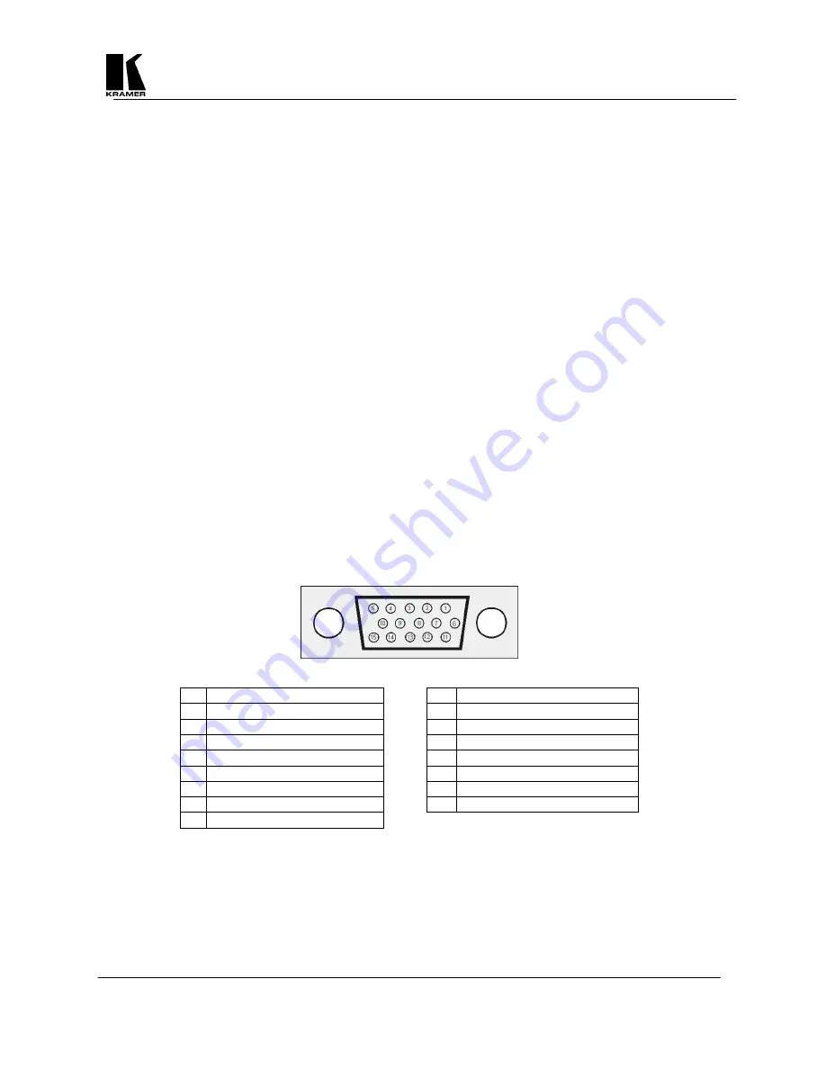
13.1 Computer Input
Input to the Scan Converter is via an HD-15 connector.
Pin Use
Pin Use
1
Red 0.7v max. / 75 Ohms
9
Passed to PC monitor pin 9
2
Green 0.7v max. / 75 Ohms
10 Ground
3
Blue 0.7v max. / 75 Ohms
11 Ground
4
ID 2, passed to PC monitor pin 4
12 ID 1, passed to PC monitor pin 12
5
Ground
13 Horizontal Sync TTL
6
Red ground
14 Vertical Sync TTL
7
Green ground
15 Passed to PC monitor pin 15
8 Blue
ground
13.2 Fuse Replacement
The Scan Converter is double-fused for added protection. The main AC fuse is located next to the On/Off
Switch on the rear panel and is easily accessible. There is also a DC fuse on the main circuit board inside the
unit, however, this rarely needs replacing. If replacement is necessary of either fuse, be sure to use the same
type and size as the original.


