


Kramer Electronics Ltd.
4
2
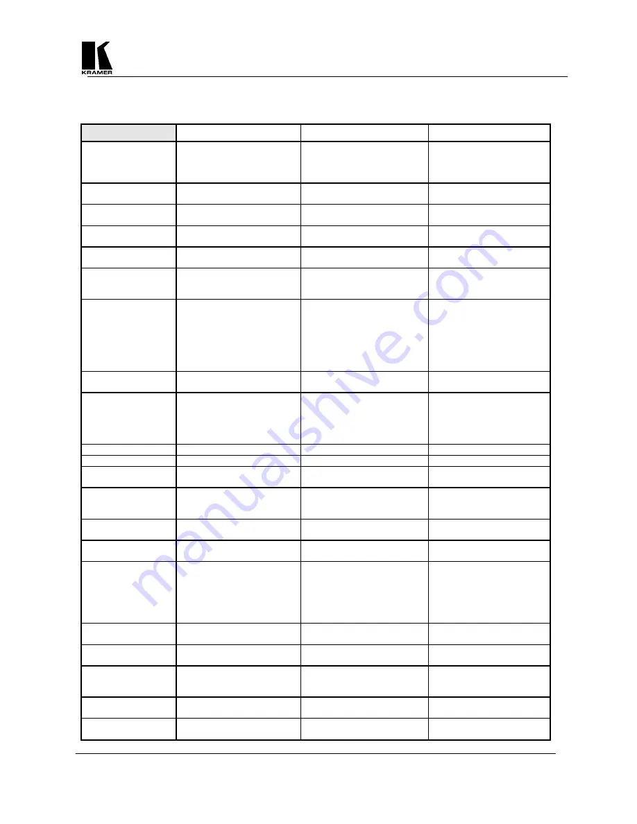
SPECIFICATIONS
VP-704SC VP-705SC VP-706SC
Computer Input
RGB with HV Sync
RGB with Composite Sync
RGB with Sync on Green
RGB with HV Sync
RGB with Composite Sync
RGB with Sync on Green
RGB with HV Sync
RGB with Composite Sync
RGB with Sync on Green
Maximum Input
Resolution
1600x1200
1280x1024 1600x1200
Maximum Vertical
Refresh Rate
150Hz
150Hz 150Hz
Maximum Horizontal
Scan Rate
100KHz
100KHz 100KHz
Computer Input
Connection
HD15 Jack
HD15 Jack
HD15 Jack
Input Level
RGB @ 0.7V Peak Level
H&V Sync @ TTL
RGB @ 0.7V
H&V Sync @ TTL
RGB @ 0.7V
H&V Sync @ TTL
Video Outputs
VGA Loop-thru
Composite Video @ 1V P-P
S-Video @ 1V P-P
RGBS @ 0.7V P-P, TTL Sync
RGBHV @ 0.7V P-P, TTL Sync
YUV (Y,R-Y,B-Y)
VGA Loop-thru
Composite Video @ 1V P-P
S-Video @ 1V P-P
RGBS @ 0.7V P-P, TTL Sync
RGBHV @ 0.7V P-P, TTL Sync
YUV (Y,R-Y,B-Y)
VGA Loop-thru
Composite Video @ 1V P-P
S-Video @ 1V P-P
RGBS @ 0.7V P-P, TTL Sync
RGBHV @ 0.7V P-P, TTL Sync
YUV (Y,R-Y,B-Y)
Video Standard
NTSC/PAL Switchable
NTSC/PAL Switchable
NTSC/PAL Switchable
Output Connectors
Composite Video on BNC,
S-Video on 4-Pin Mini-DIN
RGBS on BNCs
YUV (shares RGBS BNCs)
Composite Video on BNC
S-Video on 4-Pin Mini-DIN,
RGBS on BNCs
YUV (shares RGBS BNCs)
Composite Video on BNC
S-Video on 4-Pin Mini-DIN,
RGBS on BNCs
YUV (shares RGBS BNCs)
Genlock Signal
N/A
Composite or Blackburst 1V P-P Composite or Blackburst 1V P-P
Genlock Connection
N/A
2 BNC (Loop-through)
2 BNC (Loop-through)
Image Scaling
Proprietary Method
Proprietary Method
Proprietary Method
AutoTrack™
Proprietary Automatic Image
Sizing and Positioning
Proprietary Automatic Image
Sizing and Positioning
Proprietary Automatic Image
Sizing and Positioning
Zoom & Pan
2X
2X 2X
Flicker Reduction
2, 4 or 6-Line
2, 4 or 6-Line
2, 4 or 6-Line
Control Type
Manual Front Panel Buttons
(with Front Panel LCD Display)
RS-232 Serial
Infrared Remote Control
Manual Front Panel Buttons
(with Front Panel LCD Display)
LCD Display
RS-232 Serial
Infrared Remote Control
Manual Front Panel Buttons
(with Front Panel LCD Display)
LCD Display
RS-232 Serial
Infrared Remote Control
Subcarrier Lock
Locked to Line Frequency
Locked to Line Frequency
Locked to Line Frequency
Weight
2.0 kg (4.4lbs.) Approx.
2.0 kg (4.4lbs.) Approx.
2.0 kg (4.4lbs.) Approx.
Dimensions (HxWxD)
19" x 7" x 1.75” (1RU)
(482mm x 178mm x 44.5mm)
19" x 7" x 1.75” (1RU)
(482mm x 178mm x 44.5mm)
19" x 7" x 1.75” (1RU)
(482mm x 178mm x 44.5mm)
Power Source
100-240VAC, 50/60 Hz
100-240VAC, 50/60 Hz
100-240VAC, 50/60 Hz
Power Consumption
650mA
650mA 650mA


