


Kramer Electronics Ltd.
TP-594Txr, TP-594Rxr
– Defining the Transmitter and Receiver
5
Defining the Transmitter and
Receiver
This section defines
TP-594Txr
transmitter and
TP-594Rxr
receiver.
Defining TP-594Txr
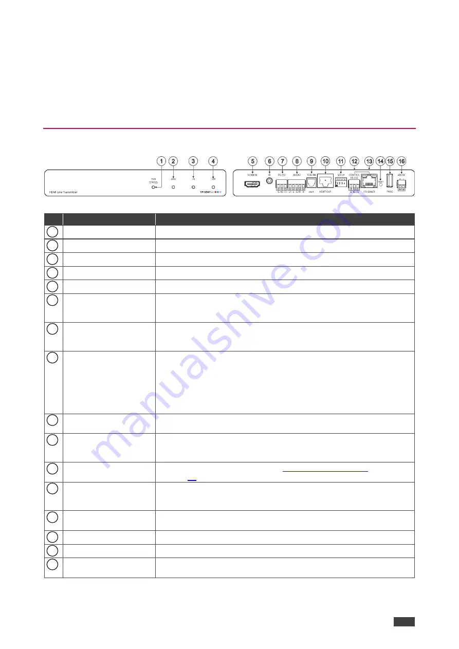
Figure 1: TP-594Txr HDMI Line Transmitter
#
Feature
Function
POE STATUS LED
Lights green when power is provided over the HDBT connection.
LINK LED
Lights green when the HDBT link is valid.
IN LED
Lights green when an active source device input signal is detected.
ON
LED
Lights green when the device receives power.
HDMI IN Connector
Connect to an HDMI source.
IR 3.5mm Mini Jack
Connector
Connect to an IR emitter cable to control a local device from the receiver
(
TP-594Rxr
) side or connect to an IR sensor cable to control a remote
device connected to the
TP-594Rxr
receiver.
RS-232 3-pin Terminal
Block Connector
Connect to a controller device (for example,
SL-240C
) to control a remote
device that is connected to
TP-594Rxr
via serial controller (for example,
the HDMI OUT acceptor).
AUDIO 5-pin Terminal
Block Connector
Connect to either a stereo balanced audio source or acceptor (the
connection type is defined via the embedded web pages):
•
Connect an audio source to extend an audio signal from
TP-594Txr
to the audio acceptor on the receiver side via the HDBT link.
•
Connect an audio acceptor to output the audio signal received from
the audio source on
TP-594Rxr
via the HDBT link.
TOSLINK OUT
Connector
Digital audio on a TOSLINK optical female connector, for outputting the
digital audio signal that is extended from the receiver to an audio acceptor.
HDBT OUT Connector
Connect to the RJ-45 HDBT IN connector on a receiver (for example,
TP-594Rxr
or
TP-590Rxr
) to extend the signals between the
TP-594Txr
and the receiver.
SETUP 4-way
DIP-switches
Set the operation DIP-switches (see
CONTROL RS-232
3-pin Terminal Block
Connector
Connect to a PC to control the device.
CONTROL ETHERNET
RJ-45 Connector
Connect to a PC to control the device or for LAN extension.
RESET Recessed Button
Press and hold to reset settings to factory default values.
PROG USB Port
Connect to a USB memory device to upgrade the firmware.
48V DC Power Terminal
Block Connector
Connect to the supplied power adapter.
1
2
3
4
5
6
7
8
9
10
11
12
13
14
15
16
DRAFT


