background image

17

Experts in heating

User Manual 

Twin Bio

 - PLV 09.13

5

D

esi

g

gu

idelines

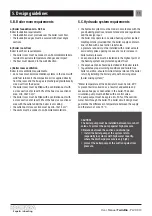
5.B. Boiler room requirements

a) Boiler foundation min. 0.05 m

Boiler foundation requirements:
•   the foundation must protrude over the boiler room fl oor;
•   the foundation edges must be secured with steel angle 

sections.

b) Boiler room fl oor 

Boiler room fl oor requirements:
•   the boiler room must be made of non-fl ammable materials, 

resistant to extreme temperature changes and impact;

•   the fl oor must descend in the well direction.

c) Boiler room ventilation

Boiler room ventilation requirements:
•   do not use mechanical ventilation systems in the room with 

solid fuel furnace if the combustion air is supplied directly 
from the room and the fl ue gas is discharged gravitationally 
via a duct from the device;

•   the boiler room must be fi tted with a ventilation duct with 

a cross section of at least 50% of the fl ue cross sectional 
area, min. 20x20 cm

2

;

•   the boiler room must be fi tted with a ventilation duct with 

a cross section of at least 25% of the fl ue cross sectional 
area with the outlet under the boiler room ceiling;

•   the outlet duct cross section must be min. 14x14 cm

2

;

•   the vents must be made of non-fl ammable materials.

5.C.  Hydraulic system requirements

•   the hydraulic system must be made in accordance with the 

good building practices, relevant standards and regulations, 
and the design input 

•   the boiler may operate in a sealed heating system (sealed 

diaphragm tank) provided that the boiler supply and return 
line is fi tted with a dual action relief valve 

•   a pressure reducer must be installed with a relief valve to 

avoid safety valve opening in case of a rapid increase in 
boiler water pressure 

•   an expansion tank must be installed in the highest point of 

the heating system and protected against frost

•   the expansion tank should be installed at the boiler return 
•   to guarantee proper working conditions and failure free 

boiler operation, ensure minimum temperature at the boiler 
return by installing the boiler pump with a mixing valve 
(boiler mixing system)*

*Water temperature at the boiler return must be min. 45°C 
to prevent boiler corrosion as a result of undesirable and 
excessive fl ue gas condensation in the boiler. The boiler 
circulation pump must be fi tted with a control valve.
The pump output must be approx. 40÷50% of the nominal 
water fl ow through the boiler. The boiler circuit design must 
guarantee the difference in temperature between the supply 
and the return of max. 15°C.

CAUTION!
The boiler pump must be installed between two cut-off 
valves. To protect the pump against high pressure 
difference between the suction and discharge:
•   install the boiler pump at the system return 

(especially in systems with high water capacity, 
where the discharge pressure is very high);

•   protect the boiler pump at the suction against low 

pressure.

Summary of Contents for 4062852055092

Page 1: ...E N G L I S H E N...

Page 2: ......

Page 3: ...nd The basic principles of the safe use of the boiler 1 Please read the user manual carefully before boiler start up 2 Before you start up the boiler check whether it is connected to the central heati...

Page 4: ......

Page 5: ...boiler design as a complete heating device 5 Design guidelines 6 Boiler start up operation and stop including emergency stop 7 Installation 8 Boiler operation and maintenance 9 Important notes guideli...

Page 6: ...boiler operation conforming to the User Manual guarantees safe and failure free operation and is a precondition for the manufacturer s warranty coverage The speci cations may change without notice KO...

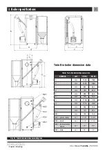
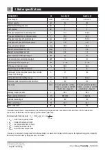
Page 7: ...data SYMBOL unit TB 16 TB 24 A mm 1383 1383 B mm 1285 1385 C mm 862 862 D mm 789 889 E mm 698 698 F mm 154 154 G mm 1106 1106 H mm 1210 1210 I mm 258 308 J mm 170 222 K1 mm 159 159 K2 power supply ca...

Page 8: ...g h 72 48 Temperature control settings range C 50 80 50 80 Minimum water temperature at boiler return C 45 45 Fuel type Class Sawdust granulate pellets made in accordance with EN 303 5 2012 Class C1 S...

Page 9: ...drzwiczki g rne automatyka kot a palnik zbiornik podajnik zsyp STB 1 2 3 4 5 6 7 8 9 4 Twin Bio boiler design as a complete heating device Fig Boiler design 1 ash pan door 2 feed door 3 top door 4 bo...

Page 10: ...DC01 powder painted 0 8 mm steel sheets boiler body insulation mineral wool Twin Bio is a boiler with a three ue gas passes combustion circuit All boiler components are MAG 135 welded Most of the boi...

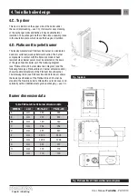
Page 11: ...Burner power must be selected on the basis of the given Twin Bio boiler unit The following diagram see Platinum Bio v02 burner dimension diagram and the following table see Platinum Bio v02 burner dim...

Page 12: ...der is a dedicated system conveying fuel from the storage hopper to the burner A 1595 mm B 88 mm Fig 02 Feeder dimension diagram 1 2 3 4 1 feed screw 2 feed duct 3 socket 4 gear motor Fig 02 Feeder co...

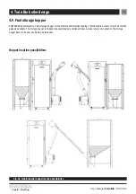
Page 13: ...pper for the ef cient and effective feeding of Platinum Bio burners It is made of DX01 galvanised sheets The storage hopper is shipped disassembled in a cardboard box A swivel chute is mounted on the...

Page 14: ...in overheating and faulty system operation 1 safety temperature limiter STB switch cover 2 safety temperature limiter STB mounting nut 3 boiler temperature sensor 4 safety temperature limiter STB tem...

Page 15: ...ter moisture dust and dirt inside the device otherwise it may result in short circuit electric shock re or damage overcurrent protection must be selected specifically for the installation boiler T boi...

Page 16: ...ing to the storage hopper repairs inspections etc Ensure suf cient space when planning and installing the boiler and its accessories in the distance required to open all boiler doors clean the combust...

Page 17: ...tandards and regulations and the design input the boiler may operate in a sealed heating system sealed diaphragm tank provided that the boiler supply and return line is tted with a dual action relief...

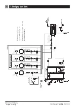
Page 18: ...ting temperature sensor Central heating temperature sensor Central heating temperature sensor Domestic hot water temperature sensor Room temperature sensor Room temperature sensor Room temperature sen...

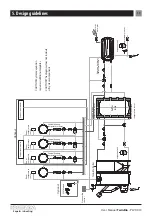
Page 19: ...ensor top buffer tank temperature sensor CAUTION System expansion requires additional modules CAUTION The diagram does not include all system components Room temperature sensor Room temperature sensor...

Page 20: ...mperature sensor Central heating temperature sensor Central heating temperature sensor GSM Module Twin Bio boiler bottom buffer tank temperature sensor bottom buffer tank temperature sensor top buffer...

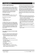
Page 21: ...ength ue shape bends inclination draught breaker etc ue cross section ue diameter ue diameter must correspond to the boiler s ue connector diameter ue internal surface roughness ue cleanness ue gas ti...

Page 22: ...length 3 15 L 40 moisture content 10 ash content 0 7 calori c value 16 5 19 MJ kg density 600 kg m Oats Pellets The Twin Bio boiler may be tted with an optional burner grate for the combustion of oat...

Page 23: ...wntimes 6 B Filling boiler and system System and boiler feed water must meet the design requirement see section 5 D Water quality requirements The difference between the feed water temperature and the...

Page 24: ...nt in sequence visually check the system after a few days of operation door and access door ue gas tightness check boiler room ventilation check boiler room lighting suitable for boiler operation and...

Page 25: ...kage auxiliary equipment failure other faults which cannot be removed during boiler operation due to safety or technical reasons Emergency procedure stop the boiler immediately use the main power swit...

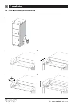
Page 26: ...26 Experts in heating User Manual Twin Bio PLV 09 13 7 Installation 7 B Top insulation installation and removal 1 2 3 4 5...

Page 27: ...27 Experts in heating User Manual Twin Bio PLV 09 13 7 Installation 7 C Top cover insulation installation and removal 1 2 3 4 5...

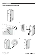
Page 28: ...28 Experts in heating User Manual Twin Bio PLV 09 13 7 Installation 7 D Block insulation installation and removal 1 2 3 4 5...

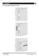
Page 29: ...29 Experts in heating User Manual Twin Bio PLV 09 13 7 Installation 7 E Front insulation installation and removal 1 2 3...

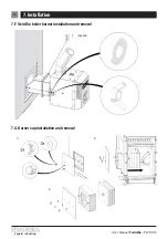
Page 30: ...30 Experts in heating User Manual Twin Bio PLV 09 13 7 Installation 7 F Twin Bio boiler burner installation and removal rope seal 1 7 G Burner cap installation and removal 1 2 3...

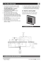
Page 31: ...ollowing order 5 2 3 4 1 7 6 For installation reverse the procedure 7 I Boiler control system installation The Twin Bio boiler control system includes a Platinum Bio control The control is a wall moun...

Page 32: ...oes not exceed 200 C Do not start the boiler if one of the following applies 1 Set the OFF mode on the control panel wait for the boiler to cool 2 Choose fuel type feed chamber 3 Place additional grat...

Page 33: ...User Manual Twin Bio PLV 09 13 7 Installation 13 pcs 16 kW 17 pcs 24 kW Combustion chamber dimensions Table Dimensions of the combustion chamber for the Twin Bio Boiler Twin Bio TB 16 TB 24 N 310 310...

Page 34: ...ulation of the boiler check and adjust burner adjust control system settings After a long boiler burner downtime the residual oxygen in boiler water and the oxygen from the air mixed with carbonic aci...

Page 35: ...35 Experts in heating User Manual Twin Bio PLV 09 13 8 Boiler operation and maintenance 1 Exchanger baf e cleaning 2 Swirl vane cleaning...

Page 36: ...36 Experts in heating User Manual Twin Bio PLV 09 13 8 Boiler operation and maintenance 3 Ceramic chamber cleaning 4 Burner grate cleaning...

Page 37: ...ration of the entire heating system check ue gas analysis and adjust the heating system control system settings burner settings etc 9 Important notes guidelines and tips Before burner start up check w...

Page 38: ...horised and trained personnel only 7 Check the wiring system and the ue system periodically 8 Do not block the vents 9 Check the burner operation and the ue gas quality adjust the burner or analyse ue...

Page 39: ...Fouled burner grate sinter on the grate Check sensor installation Replace feeder sensor Clean burner grate No indications on the display No power supply Incorrect connection of control system plugs a...

Page 40: ...ng Black smoke in the combustion chamber Not combusted fuel in the ash pan Incorrect air volume Incorrect feed and pause time for speci c power Reduce air volume check feed and pause time burner power...

Page 41: ......

Page 42: ......

Page 43: ...D E U T S C H D E...

Page 44: ......

Page 45: ...es Geb udes Grundlegende Regeln f r den sicheren Betrieb des Kessels 1 Vor der Inbetriebnahme unbedingt mit der Bedienungsanleitung bekanntmachen 2 Vor der Inbetriebnahme des Kessels ist zu pr fen ob...

Page 46: ......

Page 47: ...rojektierung 6 Inbetriebnahme Betrieb und Abschaltung des Kessels einschlie lich Nothalt 7 Montagearbeiten 8 Nutzung und Wartung des Kessels 9 Wichtige Anmerkungen Hinweise und Empfehlungen 10 Liquidi...

Page 48: ...geltenden Normen und den Regeln der Baukunst durchzuf hren Die Nutzung des Kessels in Anlehnung an diese Dokumentation garantiert einen sicheren und st rungsfreien Betrieb und stellt die Grundlage f r...

Page 49: ...in Bio SYMBOL Einheit TB 16 TB 24 A mm 1383 1383 B mm 1285 1385 C mm 862 862 D mm 789 889 E mm 698 698 F mm 154 154 G mm 1106 1106 H mm 1210 1210 I mm 258 308 J mm 170 222 K1 mm 159 159 K2 Versorgung...

Page 50: ...er R ckkehr zum Kessel C 45 45 Brennstoffart Klasse Granulat aus S gesp nen Pellets gem Norm EN 303 5 2012 Klasse C1 Granulat aus S gesp nen Pellets gem Norm EN 303 5 2012 Klasse C1 Fassungsverm gen d...

Page 51: ...iczki g rne automatyka kot a palnik zbiornik podajnik zsyp STB 1 2 3 4 5 6 7 8 9 4 Aufbau des Kessels als komplettem Heizger t Twin Bio Abbildung Aufbau des Kessels 1 T r des Aschekastens 2 T r der Be...

Page 52: ...tetes Stahlblech der St rke von 0 8 mm W rmed mmung des Kessels Mineralwolle Der Kessel Twin Bio ist ein Kessel mit 3 Rauchgasz gen Die einzelnen Kesselelemente werden mit der Methode MAG 135 verschwe...

Page 53: ...digem Stahl hergestellt Die Auswahl der Brennerleistung h ngt vom konkreten Kessel Twin Bio ab Die grundlegenden Abma e der Brenner aus der Familie Platinum Bio v02 werden auf der Abbildung Ma schema...

Page 54: ...er ist ein Brennstoffaufgeber aus einheimischer Produktion A 1595 mm B 88 mm Abbildung 02 Ma schema des Aufgebers 1 2 3 4 1 Schnecke des Aufgebers 2 Rohr des Aufgebers 3 Steckdose 4 Getriebemotor Abbi...

Page 55: ...r Brennstoffversorgung des Brenners Platinum Bio vor Der Beh lter wird aus verzinkten Blechen DX01 hergestellt Der Beh lter wird vom Hersteller im nicht montierten Zustand in einem Karton geliefert Di...

Page 56: ...e der Temperaturf hler des Kessels kann zu dessen berhitzung und einem inkorrekten Betrieb des Systems f hren 1 Abdeckung des STB 2 Befestigungsmutter des STB 3 F hler der Kesseltemperatur 4 Temperatu...

Page 57: ...Sie m ssen auf der gesamten L nge eine unbesch digte Au enisolierung besitzen 9 Es darf nicht zugelassen werden dass Wasser Feuchtigkeit oder Staub in das Innere eindringen dies k nnte Kurzschl sse el...

Page 58: ...ch ttung der Brennstoffe in den Brennstoffbeh lter Reparaturen Durchsichten usw Es ist bei der Planung des Kessels selbst und seiner Anlage auf die Sicherstellung entsprechender Abst nde zur ffnung al...

Page 59: ...ungsvorgaben des Geb udes ausgef hrt werden Der Kessel kann in geschlossenen Heizinstallationen mit geschlossenem Membrangef ausschlie lich unter der Bedingung betrieben werden dass ein thermisches Si...

Page 60: ...hler Zentralheizungs Temperaturf hler Zentralheizungs Temperaturf hler Warmwasser Temperatur f hler Zimmer temperaturf hler Zimmer temperaturf hler Zimmer temperaturf hler Zimmer temperaturf hler Zus...

Page 61: ...rs oberer Temperaturf hler des Puffers ACHTUNG Der Ausbau des Systems erfordert den Zukauf zus tzlicher Module ACHTUNG Dieses Schema ber cksichtigt nicht alle Elemente des Systems Zimmer temperaturf h...

Page 62: ...alheizungs Temperaturf hler Zentralheizungs Temperaturf hler Zentralheizungs Temperaturf hler GSM Modul Kessel Twin Bio unterer Temperaturf hler des Puffers unterer Temperaturf hler des Puffers oberer...

Page 63: ...als der Querschnitt des Fuchses Rauheit der Innen chen der Schornsteinleitung Sauberkeit des Abgasrohrs Dichtheit des Abgasrohrs Dichtungen Abdichtfugen usw Anwesenheit und Ausf hrung der Thermoisoli...

Page 64: ...ist Granulat aus S gesp nen Pellets hergestellt nach der Norm EN 14961 2 2011 Klasse A1 Durchmesser 6 1 mm 8 1mm L nge 3 15 L 40 Feuchtigkeit 10 Aschegehalt 0 7 Heizwert 16 5 19 MJ kg Dichte 600 kg m...

Page 65: ...n versorgende Wasser muss den Bedingungen entsprechen die in den Projektvorgaben genannt wurden siehe Punkt 5 D Richtlinien zur Wasserqualit t W hrend der F llung sollte der Temperaturunterschied zwis...

Page 66: ...erpr fung des Zustands der arbeitenden Installation vorzunehmen insbesondere der Dichtheit der T ren und Reinigungs ffnungen des Kessels und der Schornsteinleitung Kontrolle der Funktion der L ftungsa...

Page 67: ...ungen deren Beseitigung w hrend des Betriebs des Kessels aus technischen Gr nden oder in Hinsicht auf den Arbeitsschutz unm glich ist Im Falle von Gefahren ist sofort der Kessel abzuschalten wenn dies...

Page 68: ...68 Spezialisten f r Heizung Bedienungsanleitung Twin Bio PLV 09 13 7 Montagearbeiten 7 B Montage Demontage der oberen Isolierung 1 2 3 4 5...

Page 69: ...69 Spezialisten f r Heizung Bedienungsanleitung Twin Bio PLV 09 13 7 Montagearbeiten 7 C Montage Demontage des oberen Deckels 1 2 3 4 5...

Page 70: ...70 Spezialisten f r Heizung Bedienungsanleitung Twin Bio PLV 09 13 7 Montagearbeiten 7 D Montage Demontage der seitlichen Isolierung 1 2 3 4 5...

Page 71: ...71 Spezialisten f r Heizung Bedienungsanleitung Twin Bio PLV 09 13 7 Montagearbeiten 7 E Montage Demontage der vorderen Isolierung 1 2 3...

Page 72: ...alisten f r Heizung Bedienungsanleitung Twin Bio PLV 09 13 7 Montagearbeiten 7 F Montage Demontage des Brenners des Kessels Twin Bio Dichtungsschnur 1 7 G Montage Demontage der Verblendung des Brenner...

Page 73: ...t in umgekehrter Reihenfolge 7 I Montage der Kesselautomatik Die Automatik des Kessels Twin Bio besteht aus dem Regler Platinum Bio Dieser Regler ist zur Wandmontage mit Hilfe von Schrauben bestimmt A...

Page 74: ...tet Verboten ist die Inbetriebnahme des Kessels wenn 1 Auf dem Steuerpult Modus OFF einstellen abwarten bis der Kessel sich abk hlt 2 Brennstoffart ausw hlen Beladekammer 3 Zus tzliche Roste in den Ke...

Page 75: ...Heizung Bedienungsanleitung Twin Bio PLV 09 13 7 Montagearbeiten 13 st ck 16 kW 17 st ck 24 kW Abma e der Brennkammer Tabelle Abma e der Brennkammer des Kessels Twin Bio Twin Bio TB 16 TB 24 N 310 310...

Page 76: ...des Kessels Einstellung des Brenners Kontrolle der Automatikeinstellungen Nach dem Abschalten des Kessels f r l ngere Zeit haben der im Kesselwasser enthaltene Restsauerstoff sowie der aus der Luft ei...

Page 77: ...77 Spezialisten f r Heizung Bedienungsanleitung Twin Bio PLV 09 13 8 Nutzung undWartung des Kessels 1 Reinigung der Trennw nde des W rmeaustauschers 2 Reinigung der Drallk rper...

Page 78: ...78 Spezialisten f r Heizung Bedienungsanleitung Twin Bio PLV 09 13 8 Nutzung undWartung des Kessels 3 Reinigung der Keramikkammer 4 Reinigung des Brennerrostes...

Page 79: ...des Brenners usw 9 Wichtige Anmerkungen Hinweise und Empfehlungen Vor der Inbetriebnahme des Kessels ist unbedingt zu pr fen ob sich Wasser in der Heizungsanlage be ndet Der Brennstoff beh lter muss...

Page 80: ...s der Zustand der Elektroanlage und der Schornsteininstallation kontrolliert werden 8 Die L ftungsgitter d rfen nicht abgedeckt oder verstellt werden 9 Zyklisch muss der Betrieb des Brenners des Heizk...

Page 81: ...en auf dem Rost Kontrolle der Korrektheit der Anschl sse des F hlers am Anschlussw rfel Messf hler des Aufgebers wechseln Brennerrost reinigen Keine Anzeige auf dem Reglerdisplay Fehlende Stromversorg...

Page 82: ...des Stopps des Aufgebers f r die einzelnen Leistungen Verringerung der Luftmenge Kontrolle der Zeiten der Zuf hrung und des Stopps des Aufgebers eventuell zu gro e Leistung des Brenners eingestellt W...

Page 83: ......

Page 84: ......

Page 85: ...R U...

Page 86: ......

Page 87: ...KOSTRZEWA Kostrzewa 1978 30 KOSTRZEWA Twin Bio Twin Bio 1 2 3 4 KOSTRZEWA 1 11 500 48 87 428 53 51 48 87 428 11 34 e mail serwis kostrzewa com pl Twin Bio KOSTRZEWA...

Page 88: ......

Page 89: ...89 Twin Bio PLV 09 13 VI Twin Bio 1 2 3 4 Twin Bio 5 6 7 8 9 10 11 12 13...

Page 90: ...90 Twin Bio PLV 09 13 1 2 3 Twin Bio 16 24 Twin Bio 1 KOSTRZEWA 2 Twin Bio 1350 900 Platinum Bio 70 1 286 Platinum Bio 13 16 17 24 3 Twin Bio EN 303 5 2012 Twin Bio Twin Bio...

Page 91: ...in Bio TB 16 TB 24 A mm 1383 1383 B mm 1285 1385 C mm 862 862 D mm 789 889 E mm 698 698 F mm 154 154 G mm 1106 1106 H mm 1210 1210 I mm 258 308 J mm 170 222 K1 mm 159 159 K2 1 1 2 1 1 2 K3 1 1 2 1 1 2...

Page 92: ...8 9 42 13 14 7 74 8 21 159 159 10 K 1 7 3 8 20 K 0 5 1 1 16 24 14 21 4 16 6 24 90 8 90 4 EN 303 5 2012 5 5 18305 72 48 C 50 80 50 80 C 45 45 pellets EN 303 5 2012 C1 pellets EN 303 5 2012 C1 286 286...

Page 93: ...93 Twin Bio PLV 09 13 4 Twin Bio drzwiczki popielnikowe drzwiczki za adunkowe drzwiczki g rne automatyka kot a palnik zbiornik podajnik zsyp STB 1 2 3 4 5 6 7 8 9 4 Twin Bio 1 2 3 4 5 6 7 8 9 STB...

Page 94: ...94 Twin Bio PLV 09 13 4 Twin Bio 4 A P265GH DIN EN 10028 5 S235JR EN 10025 2 4 P265GH DIN EN 10028 5 DC01 0 8 Twin Bio MAG 135 4 B S235JR EN 10025 2 3 1 2 3...

Page 95: ...tinum Bio v02 Platinum Bio v02 Platinum Bio v02 Platinum Bio v02 Platinum Bio v02 Twin Bio 7 J Platinum Bio v02 PB 16 v02 PB 24 v02 A mm 245 245 B mm 222 222 B1 mm 180 180 C mm 258 258 D mm 497 537 E...

Page 96: ...96 Twin Bio PLV 09 13 4 Twin Bio 4 E A 1595 mm B 88 mm 02 1 2 3 4 1 2 3 4 02 4 H...

Page 97: ...97 Twin Bio PLV 09 13 4 Twin Bio 4 F KOSTRZEWA 286 Platinum Bio DX01 02 Twin Bio...

Page 98: ...98 Twin Bio PLV 09 13 4 Twin Bio 4 G STB 90 C STB STB 3 STB 4 7 pok nak czu czu kan ele ogr bez obu tem 1 2 3 4 5 6 7 1 STB 2 STB 3 4 STB 5 6 STB 7 4 H 1 230 50 2 3...

Page 99: ...Twin Bio 4 5 6 7 8 9 T T CO STB N1 N1 N N PE PE PE N N L L N N PE PE 1 2 3 4 5 7 6 N N N N PE PE PE PE Pco CWU 230 Tcwu Tcwu GND GND foto Pcwu Pco Pcwu 10 11 4 I Twin Bio Platinum Bio Platinum Bio LB5...

Page 100: ...100 Twin Bio PLV 09 13 5 5 5 A a A1 mm 500 B1 mm 700 C1 mm 500 H1 mm 2000 g mm 50...

Page 101: ...6 Uruchamianie 101 Twin Bio PLV 09 13 5 B 0 05 50 20x20 2 25 14x14 2 5 C 45 C 40 50 15 C...

Page 102: ...102 Twin Bio PLV 09 13 5 M M M c w u Platinum Bio GSM Twin Bio...

Page 103: ...103 Twin Bio PLV 09 13 5 c w u Platinum Bio M M M GSM Twin Bio...

Page 104: ...104 Twin Bio PLV 09 13 5 M M M Platinum Bio GSM Twin Bio c w u...

Page 105: ...105 Twin Bio PLV 09 13 5 5 D pH 8 5 20 f 0 05 60 KOSTRZEWA 5 E Twin Bio 100 C Twin Bio Twin Bio...

Page 106: ...win Bio PLV 09 13 5 0 14 0 12 7 1 A 2 6 Q n H 0 5 2 Q n 900 1880 n 900 H 5 F Twin Bio pellets EN 14961 2 2011 A1 6 1 8 1 3 15 L 40 10 0 7 16 5 19 M 600 Twin Bio 50 50 12 7 J Twin Bio 7 K 20 18 8 Kostr...

Page 107: ...107 Twin Bio PLV 09 13 5 6 5 G 5 H 6 6 A 6 B 5 D 30 C 6 C...

Page 108: ...108 Twin Bio PLV 09 13 6 6 D KOSTRZEWA www kostrzewa com pl ON 6 E...

Page 109: ...109 Twin Bio PLV 09 13 6 7 7 7 A...

Page 110: ...110 Twin Bio PLV 09 13 7 7 B 1 2 3 4 5...

Page 111: ...111 Twin Bio PLV 09 13 7 7 C 1 2 3 4 5...

Page 112: ...112 Twin Bio PLV 09 13 7 7 D 1 2 3 4 5...

Page 113: ...113 Twin Bio PLV 09 13 7 7 E 1 2 3...

Page 114: ...114 Twin Bio PLV 09 13 7 7 F 1 7 G 1 2 3...

Page 115: ...115 Twin Bio PLV 09 13 7 7 H Twin Bio 1 2 3 4 5 6 7 Platinum Bio 5 2 3 4 1 7 6 7 I Twin Bio Platinum Bio Platinum Bio Platinum Bio Twin Bio...

Page 116: ...116 Twin Bio PLV 09 13 7 7 J 2 1 2 1 1 2 3 4 5 6 7 K 200 C 1 OFF 2 3 4 5 6 7 8 ON 9 70 C 10...

Page 117: ...117 Twin Bio PLV 09 13 7 13 16 kW 17 24 kW Twin Bio Twin Bio TB 16 TB 24 N 310 310 O 440 440 P 338 438...

Page 118: ...118 Twin Bio PLV 09 13 8 8 1 8 A 8 B a 6 STB 12 STB 1 Platinum Bio v02 2 8 C a...

Page 119: ...119 Twin Bio PLV 09 13 8 1 a 2...

Page 120: ...120 Twin Bio PLV 09 13 8 3 4...

Page 121: ...121 Twin Bio PLV 09 13 8 9 24 08 1991 81 11 06 2006 80 06 Platinum Bio 9 60 C...

Page 122: ...122 Twin Bio PLV 09 13 10 11 12 10 11 1 2 3 4 5 6 7 8 9 10 11 12 13 14 12 45 C...

Page 123: ...123 Twin Bio PLV 09 13 13 13 a STB STB...

Page 124: ...124 Twin Bio PLV 09 13 13...

Page 125: ......

Page 126: ......

Reviews: