TP-6865 4/14
22 Section 4 Communications
4.2.2
Modbus Connection
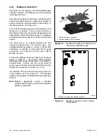
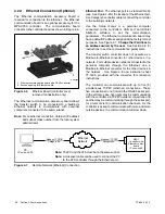
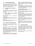
See Figure 4-2 and Figure 4-3 for the RS-485 Modbus
connector location. The Modbus port on the controller
circuit board is Port 0.
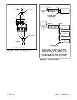
Use serial connections to TB2 on the controller board to
connect the transfer switch to a personal computer for
system monitoring, the optional remote annunciator, or
a Modbus network. See Figure 4-5.
A 121 ohm terminating resistor is recommended on the
last device in a network. If there is only one device, a
terminating resistor may be required depending on the
cable distance and communication speed. Long cables
and high speeds will increase the need for a terminating
resistor.
The serial port is an isolated RS-485 port with
connection speeds of 9.6, 19.2, and 57.6 kbps. Use
shielded twisted-pair cable to connect to the RS-485
connectors on controller terminal strip TB2 for serial
connections. For connection to a PC, use a USB to
RS-485 converter.
Connect the Modbus input and output to the terminals
shown in Figure 4-4. Use #12-24 AWG shielded,
twisted-pair wire. Belden cable #9841 or equivalent is
recommended. Connect one end of the shield to
ground. Leave the other end of the shield disconnected.
Tighten the connections to 0.5 Nm (4.4 in. lb.).
Use Modbus
r
RTU (remote terminal unit) protocol for
communication over the serial port. The Modbus
registers are available in the Modbus Protocol Manual,
TP-6113.
Note:
Modbus
r
applications require a Modbus
software driver written by a trained and qualified
systems programmer.
1. RS-485 Modbus connections
2. Access opening for RS-485 cables
GM85884
1
2
Figure 4-2
Modbus Connections (controller cover
removed for illustration only)
1. Modbus communication RS-485 connector
GM89713
1
Figure 4-3
Modbus Connector on the Controller
Circuit Board
Summary of Contents for Decision-Maker MPAC 750
Page 2: ......
Page 30: ...TP 6865 4 14 30 Section 4 Communications Notes ...
Page 39: ...TP 6865 4 14 39 Section 6 Accessories Figure 6 9 SPD Wiring Diagram GM89992 ...
Page 42: ...TP 6865 4 14 42 Section 6 Accessories Notes ...
Page 45: ...TPMPFP 6865 4 14 45 Notes ...
Page 46: ...TPMPFP 6865 4 14 46 Notes ...
Page 47: ......


