TP-6865 4/14
19
Section 3 Settings
3.6.1
Input Functions
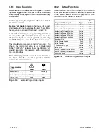
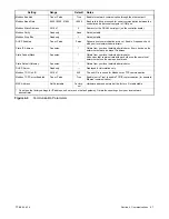
Available input functions are shown in Figure 3-4. Some
inputs will trigger an indicator LED on the user interface
and/or display a message on the LCD screen when they
are activated.
All of the inputs may be assigned to either one or both of
the common alarms.
Remote Test Input.
Activating the input starts a test,
and deactivating the input stops the test. Tests follow
the sequence described in Sections 1.4 and 2.2.3.
If a local test is already running, activating the remote
test input will stop the local test. A remote test can be
stopped locally, if necessary, by pressing and holding
the TEST button on the controller for about 2 seconds.
The default type for a remote test is “unloaded.” To
change the remote test type, use a computer and
Kohler
r
SiteTech
t
Software to set the Remote Test
Loaded parameter. Alternatively, set the remote test
type over Modbus.
The optional programmable exerciser uses the remote
test input. See the instructions provided with the
exerciser for more information.
Programmable
Inputs
LED
«
LED
Inhibit Transfer
(maintenance mode)
None
Flashing
Remote Common Alarm
Steady
None
Remote Test
None
None
Figure 3-4
Available Programmable Inputs
3.6.2
Output Functions
Output functions are shown in Figure 3-5. Information
about selected output functions is shown below. Refer
to the section number shown in Figure 3-5 for more
information about the output function.
Programmable Output
Type
See
Section
Aux Switch Fault
Fault
1.7
Aux Switch Open
Fault
1.7
Common Alarm Active (1 and 2)
Fault
3.7
Contactor in Preferred Position
Monitor
—
Contactor in Source E Position
Monitor
—
Contactor in Source N Position
Monitor
—
Contactor in Standby Position
Monitor
—
Exerciser Active
Monitor
2.2.2
Fail to Acquire Standby
Fault
1.7
Fail to Transfer
Fault
1.7
In-Phase Monitor Sync
Control
3.3.3
Not in Auto
Monitor
1.3.2
Source E (Phase) Rotation Error
Fault
—
Source N (Phase) Rotation Error
Fault
—
Test Mode Active
Monitor
1.4
Figure 3-5
Available Programmable Outputs
Summary of Contents for Decision-Maker MPAC 750
Page 2: ......
Page 30: ...TP 6865 4 14 30 Section 4 Communications Notes ...
Page 39: ...TP 6865 4 14 39 Section 6 Accessories Figure 6 9 SPD Wiring Diagram GM89992 ...
Page 42: ...TP 6865 4 14 42 Section 6 Accessories Notes ...
Page 45: ...TPMPFP 6865 4 14 45 Notes ...
Page 46: ...TPMPFP 6865 4 14 46 Notes ...
Page 47: ......

