TP-6865 4/14
41
Section 6 Accessories
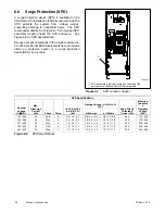
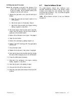
SPD Replacement Procedure
Note:
The cartridges are keyed for the phases or the
neutral. Be sure to obtain the correct service part
for each cartridge. See the transfer switch parts
catalog for service part numbers.
1. Disable the generator set to prevent starting as
follows:
a. Move the generator set master switch to the
OFF position.
b. Disconnect power to the battery charger.
c. Disconnect the generator set engine starting
battery, negative (--) lead first.
2. Disconnect power to the transfer switch: Open the
normal and emergency source circuit breakers
upstream of the transfer switch.
3. Remove the enclosure’s inner panel , if equipped.
4. Open the fuse holder.
5. Remove the cartridge by pulling straight out.
6. Replace the SPD cartridge with the appropriate
service part.
7. Close the fuse holder.
8. Replace the enclosure’s inner panel, if equipped.
9. Reconnect power to the transfer switch by closing
the normal and emergency source circuit breakers.
10. Check the SPD status indicators.
11. Reconnect the generator set engine starting
battery, negative (--) lead last.
12. Reconnect power to the battery charger.
13. Close and lock the ATS enclosure door.
14. Move the generator set master switch to the AUTO
position.
6.7
User Interface Cover
The gasket-sealed, hinged user interface cover
prevents unauthorized access to the transfer switch
controls and protects the user interface from harsh
environmental conditions. Use a customer-supplied
padlock to lock the cover.
NEMA 3R enclosures include a cover as standard
equipment.
Summary of Contents for Decision-Maker MPAC 750
Page 2: ......
Page 30: ...TP 6865 4 14 30 Section 4 Communications Notes ...
Page 39: ...TP 6865 4 14 39 Section 6 Accessories Figure 6 9 SPD Wiring Diagram GM89992 ...
Page 42: ...TP 6865 4 14 42 Section 6 Accessories Notes ...
Page 45: ...TPMPFP 6865 4 14 45 Notes ...
Page 46: ...TPMPFP 6865 4 14 46 Notes ...
Page 47: ......

