TP-6865 4/14
17
Section 3 Settings
Section 3 Settings
3.1
Introduction
The Decision-Maker
r
MPAC 750 controller is factory set
for your transfer switch. This section lists factory
settings and adjustment ranges.
If necessary, some settings can be changed using a
personal computer and Kohler
r
SiteTech
r
software or
over Modbus
r
. SiteTech software is only available to
Kohler authorized distributors and dealers.
Use a USB cable with a male mini-B connector to
connect the controller to a laptop computer. The USB
connector is located on the front of the controller. See
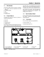
Figure 1-1.
Using Modbus
Commercially available programs can be used to read
and change some settings over Modbus. For other
Modbus applications, the Modbus master must be
programmed to read the Modbus registers. Modbus
registers are published in TP-6113, Modbus Protocol
Operation Manual. A system designer trained in the
application of Modbus protocol must write and
thoroughly test the program before implementation.
3.2
System Setup
The transfer switch is factory-set with default settings for
time delays and other parameters. See Section 1 for the
default settings. Settings can be adjusted, if necessary
using a personal computer and Kohler
r
SiteTech
t
software or over Modbus. SiteTech software is available
to Kohler authorized distributors and dealers.
Note:
Use caution when changing transfer switch
settings. The source voltage and frequency
settings must match the values shown on the
transfer switch nameplate.
3.3
System Parameters
The transfer switch is factory-set for the transfer switch
model and rating. System parameters should not
require adjustment.
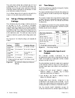
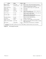
The system parameter factory settings are shown in
Figure 3-1. Note that some settings are not adjustable.
System Parameter
Factory Setting
Transition type, standard
See the ATS
nameplate
Single/three phase
Operating voltage
Operating frequency (50 or 60 Hz)
Rated current
Transfer mode
(automatic or non-automatic)*
Phase rotation*
ABC
Commit to transfer*
No
Operating mode*
Utility-to-Generator
In-phase monitor
Disabled
In-phase monitor transfer angle
5
_
* Not adjustable.
Figure 3-1
System Parameters
3.3.1
Transition Type, Standard
The MPAC 750 controller is only available for
standard-transition
model
transfer
switches.
Standard-transition models (also referred to as open
transition) use a break-before-make transfer that does
not require source synchronization for transfer between
available sources.
Note:
The transition type is determined by the ATS
model. Do not change the transition type.
3.3.2
Commit to Transfer: No
This setting is factory set to No and is not adjustable. If
the preferred source returns returns during the
transfer-to-standby time delay, the transfer sequence is
cancelled and the load is not transferred to the standby
source.
3.3.3
In-Phase Monitor
The in-phase monitor can be enabled or disabled for
standard-transition models.
The in-phase monitor
operates prior to transfer when both sources are
available. Transfer is inhibited while both sources are
greater than 2 cycles apart. If the connected source falls
below the undervoltage dropout setting, the in-phase
monitor terminates and allows transfer.
Summary of Contents for Decision-Maker MPAC 750
Page 2: ......
Page 30: ...TP 6865 4 14 30 Section 4 Communications Notes ...
Page 39: ...TP 6865 4 14 39 Section 6 Accessories Figure 6 9 SPD Wiring Diagram GM89992 ...
Page 42: ...TP 6865 4 14 42 Section 6 Accessories Notes ...
Page 45: ...TPMPFP 6865 4 14 45 Notes ...
Page 46: ...TPMPFP 6865 4 14 46 Notes ...
Page 47: ......


