TP-6865 4/14
15
Section 2 Sequence of Operation
Section 2 Sequence of Operation
2.1
Controller Power--up/Reset
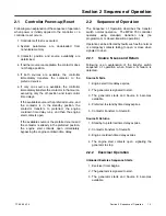
Following is an explanation of the sequence of operation
when power is initially applied to the controller or a
controller reset occurs.
1. Controller self test is executed.
2. System parameters are downloaded from
nonvolatile memory.
3. Contactor position and source availability are
determined.
4. If neither source is acceptable, the contactor does
not change position.
5. If both sources are available, the controller
immediately transfers the contactor to the
preferred source.
6. If only one source is available, the controller
immediately transfers the contactor to that source,
executing only the off-position and load control
time delays.
If the available source is the preferred source, and
the contactor is in the standby position, the
contactor transfers to preferred, the engine
cooldown time delay runs, and then the engine
start contacts open.
If the available source is the preferred source and
the contactor is already in the preferred position,
the engine start contacts open immediately,
bypassing the engine cooldown time delay.
2.2
Sequence of Operation
The Sequence of Operation describes the transfer
switch normal operation. The MPAC 750 controller
operates
using
standard
transition
only
(no
programmed- or closed-transition operation).
Operation can be affected by faults such as the normal
or emergency contacts failing to open or close when
signaled to do so.
2.2.1
Source N Loss and Return
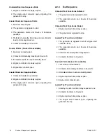
Following is an explanation of the transfer switch
sequence of operation when Source N failure is
detected.
Source N Fails
1. Engine start time delay expires.
2. The generator is signaled to start.
3. The generator starts and Source E becomes
available.
4. Preferred-to-standby time delay expires.
5. Contactor transfers to Source E.
Source N Returns
1. Standby-to-preferred time delay expires.
2. Contactor transfers to Source N.
3. Engine cooldown time delay expires.
4. The engine start contacts open, signaling the
generator to stop.
2.2.2
Exerciser Operation
Unloaded Exercise Sequence Starts
1. Exerciser timer begins.
2. The generator is signaled to start.
3. The generator starts and Source E becomes
available.
Summary of Contents for Decision-Maker MPAC 750
Page 2: ......
Page 30: ...TP 6865 4 14 30 Section 4 Communications Notes ...
Page 39: ...TP 6865 4 14 39 Section 6 Accessories Figure 6 9 SPD Wiring Diagram GM89992 ...
Page 42: ...TP 6865 4 14 42 Section 6 Accessories Notes ...
Page 45: ...TPMPFP 6865 4 14 45 Notes ...
Page 46: ...TPMPFP 6865 4 14 46 Notes ...
Page 47: ......


