TP-6865 4/14
18 Section 3 Settings
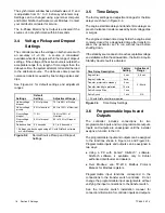
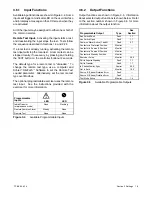
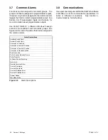
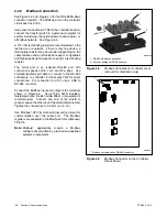
The synchronism window has a default value of 5
_
and
is adjustable from 15
_
to 5
_
before synchronism only.
Settings can be changed using a personal computer
and Kohler SiteTech software or over Modbus. Contact
your distributor or dealer for service.
The In-Phase Monitor Sync Output is activated if the
sources do not synchronize within 60 seconds.
3.4
Voltage Pickup and Dropout
Settings
The controller senses the voltage on both sources with
an accuracy of
±
0.5%.
A source is considered
available when its voltage is within the range of dropout
settings. If the voltage of the active source is outside the
acceptable range for a length of time longer than the
debounce time, the system attempts to transfer the load
to the alternate source. The debounce time prevents
nuisance transfers caused by brief voltage spikes and
dips.
See Figure 3-2 for default settings and adjustment
ranges.
Settings
Default
Setting
Adjustment Range
[
Under voltage
dropout
90% of pickup
75% to 98% of Pickup
Under voltage
pickup
90% of nominal
85% to 100% of Nominal
Over voltage
dropout
115%
106% to 135% of
Nominal
Over voltage
pickup
95% of dropout
95 to 100% of Dropout
Debounce time
0.5 seconds
0.1 to 9.9 seconds
[
Settings can be changed using a PC with SiteTech software
or over Modbus.
Figure 3-2
Normal Source Pickup and Dropout
Settings
3.5
Time Delays
The factory settings and adjustment ranges for the time
delays are shown in Figure 3-3.
The engine start time delay and transfer time delays can
prevent nuisance transfers caused by brief voltage dips
or surges.
The engine cooldown time delay holds the engine start
contacts closed for a designated time after transfer to
allow the generator set to run without load before
shutting down.
If the standby source does not reach acceptable voltage
and stabilize within the allowed time, the Fail to Acquire
Standby Source fault is activated.
Time Delay Description
Factory
Setting
Adjustment
Range
[
Engine Start
3 sec
0--6 sec
Engine Cooldown
5 min.
0--60 min
Transfer, preferred to standby
3 sec
Transfer, standby to preferred
15 min
Fail to Acquire Stby
1 min
Fail to Synch
1 min
NA
[
PC with SiteTech software required.
Figure 3-3
Time Delay Settings
3.6
Programmable Inputs and
Outputs
The
controller
includes
connections
for
two
programmable inputs and two programmable outputs.
Inputs and outputs are unassigned until the installer
assigns a function to the I/O.
The programmable inputs and outputs can be assigned
to the functions shown in Figure 3-4 and Figure 3-5.
Programmable inputs and outputs can be assigned in
two ways:
D
Using a PC with Kohler
r
SiteTech
t
software.
SiteTech software is available only to Kohler
authorized distributors and dealers.
D
Over Modbus; see TP-6113, Modbus Protocol
Manual, for Modbus registers.
Programmable input functions correspond to the
connections to the transfer switch controller. Do not
change the programmable input assignments without
verifying the input connections to the transfer switch.
See the transfer switch installation manual for
connection information for controller inputs and outputs.
Summary of Contents for Decision-Maker MPAC 750
Page 2: ......
Page 30: ...TP 6865 4 14 30 Section 4 Communications Notes ...
Page 39: ...TP 6865 4 14 39 Section 6 Accessories Figure 6 9 SPD Wiring Diagram GM89992 ...
Page 42: ...TP 6865 4 14 42 Section 6 Accessories Notes ...
Page 45: ...TPMPFP 6865 4 14 45 Notes ...
Page 46: ...TPMPFP 6865 4 14 46 Notes ...
Page 47: ......


