KNIGHT D-SERIES SERVO HOIST OPERATION MANUAL
SECTION 5
SOFTWARE
81
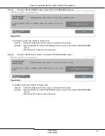
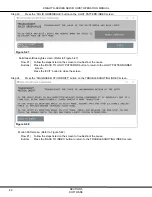
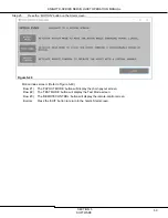
Step 36.
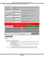
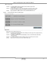
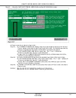
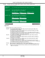
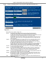
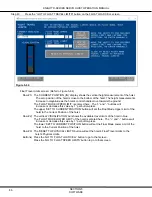
Press the “INLINE HANDLE SETUP” button on the HOIST CONFIGURATION INDEX screen.
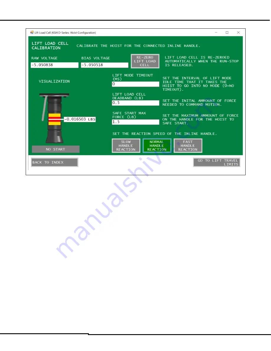
Figure 5-60
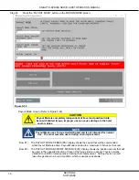
Lift Load Cell screen: (Refer to Figure 5-60)
Row #1) The ‘RAW VOLTAGE’ display shows the current voltage of the lift load cell. This is the
load cell that measures the force being exerted on the Inline Handle’s grip.
The ‘BIAS VOLTAGE’ display shows the voltage of the lift load cell when there is no force
being exerted on it.
The ‘RE-ZERO LIFT LOAD CELL’ button should only be pressed if you need to re-calibrate
the lift load cell. Please ensure that there is NO force applied to the Inline Handle before
this button is pressed. Also, please note that the lift load cell is automatically re-zeroed
every time the Run-Stop button is released.
Row #2) The Inline Handle grip ‘VISUALIZATION’ shows the amount of force applied in white, the set
Deadband in red, and the Safe Start Max Force in yellow (this band will only be visible when
the Run-Stop is pressed).
The ‘LIFT MODE TIMEOUT (MS)’ display allows setting a sleep time in milliseconds. If there
have been no commands for the given timeout, the hoist will go out of Lift mode, disabling
the drive and setting the holding brake. A zero timeout will disable this function.
Row #3) The ‘LIFT LOAD CELL DEADBAND (LB)’ sets the minimum amount of force required on the
Inline Handle to initiate motion.
Row #4) The ‘SAFE START MAX FORCE (LB)’ display shows the maximum amount of force allowed
on the Inline Handle when the trigger is pulled. Typically, if this force is exceeded, the green
light will flash indicating an Unsafe Start condition. The force on the handle must be reduced
to the acceptable range.
(Refer to Figure 5-60)

