SECTION 7
HIGH PRESSURE WATER
May 2003
p. 7-10
49831951
7.2.5 Plunger and Hydraulic Cartridge Removal and Installation
1.
Remove HP and LP piping/ hose, then remove HP cylinder jug following
procedure 7.2.2 above.
2.
Remove the proximity switch on the intensifier side nearest HP cylinder
to be serviced. This procedure will allow hydraulic oil to drain to tank
and will minimize oil spillage. Draining takes about 5 minutes. Remove
cartridge retainer flange from hydraulic cylinder head by first removing
retaining ring using a flat blade screwdriver. Wipe and clean surfaces,
weep holes, and grooves in cartridge retainer flange. Check retainer
flange for cracks.
3.
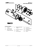
Using cartridge/plunger removal tool threaded to the seal cartridge, pull
the cartridge outward over the plunger. Seals in the hydraulic cartridge
can be removed and replaced, or the entire cartridge can be replaced. It
is recommended that at least one spare cartridge be kept on hand, ready
to install. See Section 7.3.6 for servicing hydraulic seal cartridge.
4.
With the cartridge removed, the plunger can be removed with the
cylinder head in place. Slide the cartridge/plunger removal tool over the
plunger, with the hex-shaped smaller end toward the plunger button.
Note orientation of plunger button retainer pins (6 each), then align hex
flats of tool with pins. Force tool by hand under pins, then rotate tool
slightly to cause pins to retract enough to release plunger. Plunger can
now be extracted from hydraulic piston. See Section 7.3.5 for servicing
the plunger.
5.
To install new plunger, slip cartridge/plunger removal tool over plunger,
hex end toward plunger button, to help center plunger in cylinder head.
Position plunger in mating pocket of piston, then force into place by
hand. Using a flashlight, verify that all 6 pins are equally extended to
grip plunger button.
6.
Lubricate exposed surfaces of seals in hydraulic seal cartridge with food
grade grease and slide cartridge over plunger into cylinder head cavity.
7.
Thoroughly clean cartridge retainer flange, including cross-drilled weep
holes. Install flange and internal retaining ring, making sure that the
retaining ring seats fully inside its groove. Note that hydraulic cartridge
O-rings may take up clearance. To install retaining ring, first tap lightly
on retainer flange using plunger removal tool. This will compress
cartridge O-rings enough to get retaining ring started in groove. Push on
outer edge of retainer flange with a flat bladed screwdriver while working
one end of retaining ring into groove. Retainer flange should tilt or tip
enough to allow retaining ring to move into its groove. Continue working
ring into groove while tilting flange until retaining ring is fully installed.
8.
Install HP cylinder jug to hydraulic cylinder head per paragraph 7.2.2.
Summary of Contents for STREAMLINE SL-IV PLUS
Page 44: ...SECTION 6 LOW PRESSURE WATER May 2003 6 4 05148390 Figure 6 2 LP Cutting Water Supply Circuit ...
Page 78: ...SECTION 7 HIGH PRESSURE WATER May 2003 p 7 30 49831951 ...
Page 82: ...SECTION 8 ELECTRICAL SYSTEM Aug 2002 p 8 4 49836323 ...
Page 111: ...SECTION 12 PARTS LISTS July 2003 page 12 5 49836349 ...
Page 113: ...SECTION 12 PARTS LISTS July 2003 page 12 7 49836349 ...
Page 115: ...SECTION 12 PARTS LISTS July 2003 page 12 9 49836349 ...
Page 117: ...SECTION 12 PARTS LISTS July 2003 page 12 11 49836349 ...
Page 119: ...SECTION 12 PARTS LISTS July 2003 page 12 13 49836349 ...
Page 121: ...SECTION 12 PARTS LISTS July 2003 page 12 15 49836349 ...
Page 123: ...SECTION 12 PARTS LISTS July 2003 page 12 17 49836349 ...
Page 125: ...SECTION 12 PARTS LISTS July 2003 page 12 19 49836349 ...
Page 127: ...SECTION 12 PARTS LISTS July 2003 page 12 21 49836349 ...
Page 129: ...SECTION 12 PARTS LISTS July 2003 page 12 23 49836349 ...
Page 131: ...SECTION 12 PARTS LISTS July 2003 page 12 25 49836349 ...
Page 133: ...SECTION 12 PARTS LISTS July 2003 page 12 27 49836349 ...
Page 135: ...SECTION 12 PARTS LISTS July 2003 page 12 29 49836349 ...
Page 137: ...SECTION 12 PARTS LISTS July 2003 page 12 31 49836349 ...
Page 139: ...SECTION 12 PARTS LISTS July 2003 page 12 33 49836349 ...
Page 141: ...SECTION 12 PARTS LISTS July 2003 page 12 35 49836349 ...
Page 143: ...SECTION 12 PARTS LISTS July 2003 page 12 37 49836349 ...
Page 145: ...SECTION 12 PARTS LISTS July 2003 page 12 39 49836349 ...
Page 146: ......
Page 147: ......


